OPERATOR’S MANUAL
CMA-9000 FLIGHT MANAGEMENT SYSTEM
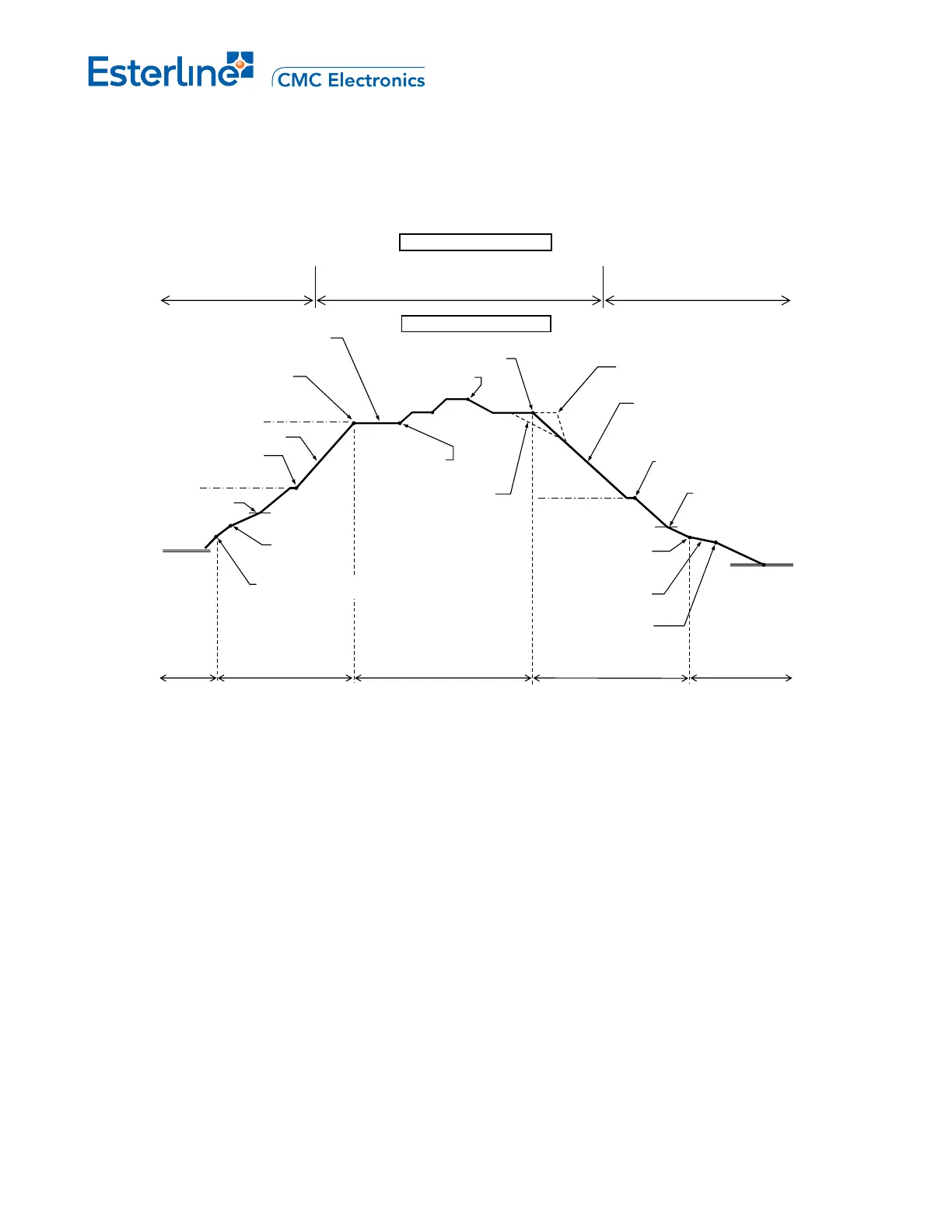
1.1.1 Vertical Profile
Figure 1 shows a typical vertical profile and its relationship with the flight phases of the lateral flight plan.
Acceleration
Height
Speed
restriction
Initial cruise flight level (CRZ ALT)
Planned Step
climb(s) (S/C)
Early descent
Late descent
Top of descent (T/D)
Top of climb (T/C)
Final approach fix
Speed restriction
Origin
Airport
Destination
Airport
Descent performance path
Takeoff
&
Lateral Flight Plan
Enroute
Arrival procedures
(STAR, TRANS, APPR, GA)
Initial
Climb
Climb Phase Cruise Phase Descent Phase
&
Lan
Approach
ding
Thrust reduction height
Manual thrust reduction to MCL
Vertical Profile
Waypoint altitude
constraint
Waypoint altitude
constraint
Departure procedures
(RWY, SID, TRANS)
End of Descent (E/D)
Aircraft reconfiguration
Climb performance path
Step descent(s)
(S/D)
FGCP altitude
FGCP altitude
FGCP altitude
Figure 1 – Typical Vertical Profile
The FMS computes the vertical profile made up of take-off and initial climb, climb, cruise, descent, and
approach flight phases. The vertical profile is based on the lateral flight plan, the environmental conditions (e.g.
wind, temperature) and the aircraft/engines’ performance data; it extends as a continuous trajectory between the
departure and destination airports. The missed approach and post-flight phases are also covered in this
section.
Page F-2
August 17, 2010