OPERATOR’S MANUAL
CMA-9000 FLIGHT MANAGEMENT SYSTEM
COMMUNICATION RADIOS (VHF RADIO)
The FMS supports the following VHF Radio in the frequency range and channel spacing specified below:
RADIO MODELS CHANNEL
RANGE
CHANNEL SPACING
VC 401B 118.000 to 136.975
25 MHz
Figure 13-2 VHF Radio Models, Channel Range and Channel Spacing
NOTE: The FMS does not accept out of range values. An error message will appear in the scratchpad if invalid
entries are made by the user. If the VHF Frequency Source Selection discrete is set then entries
made will generate an error message “RADIO TUNING DISABLED” to inform the pilot that he may no
longer tune this radio from the FMS.
The COM VHF radio equipment name can also be configured as COM1/COM2, COM3/COM4 or
VHF/VHF1.
COMMUNICATION RADIOS (VHF RADIO Page 1/2)
This page allows the pilot to control the operation of 2 VHF units.
This page allows the pilot to verify and modify the active and standby frequencies for the COM radios. It allows
the pilot to control the operation of these radios.
NOTE: Tuning commands will only be accepted if the FMS is enabled for communication radio tuning control
(e.g.: when interfaced with an external Radio Management Panel).
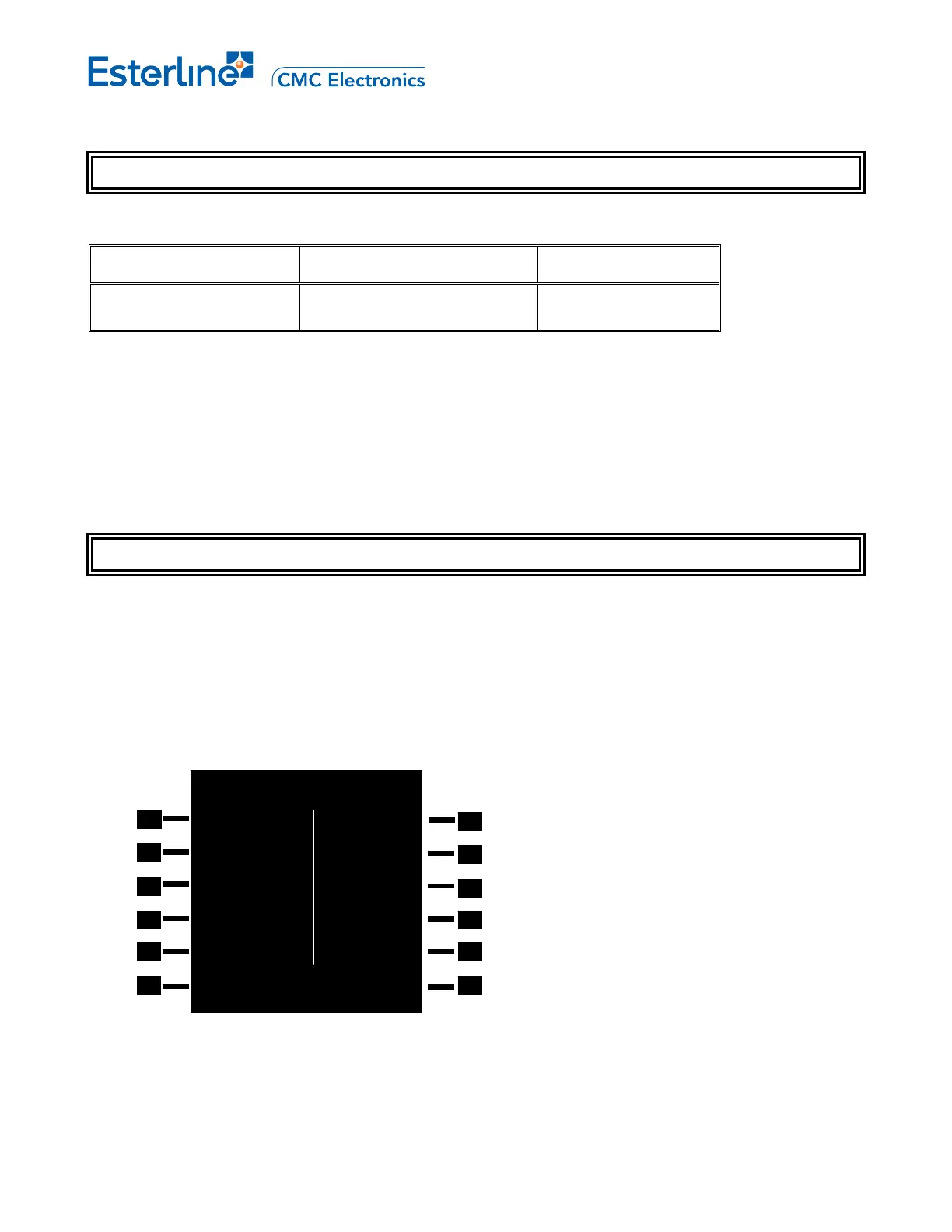
Display the first VHF 1/2 page from the horizontal configuration by pressing [RADIO], [NEXT], <VHF#>.
VHF 1/2
VHF1 VHF2
b 118.400 04 -- 151.000b
126.400 05 -- 124.650
SQUELCH SQUELCH
>OFF ON<
VOICE/DATA
DATA<
<RADIO LIBRARY>
NOTE: The COM VHF radio equipment name can also be configured as “COM" or "VHF".
The VHF ident suffix "x" (e.g. VHF, VHF1...) and the side (left or right) where the COM units appear is
depending on the installation configuration. The tables below provide examples.
Page 13-17
August 17, 2010