TX120 S3 Upgrade and Maintenance Manual 433
Appendix
Depending on BIOS settings, the shared LAN connector may also be used as
a management LAN connector. For further information, please refer to the
"D3049 BIOS Setup Utility for PRIMERGY TX140 S1 / TX120 S3 Reference
Manual".
The serial connector COM1 can be used as default interface or to communicate
with the iRMC S3.
I The chipset offers two integrated USB 2.0 Rate Matching Hubs (RMHs).
that enable lower power requirements and manages the transition of the
communication data rate from the high speed of the host controller to the
lower speed of USB full speed / low speed devices.
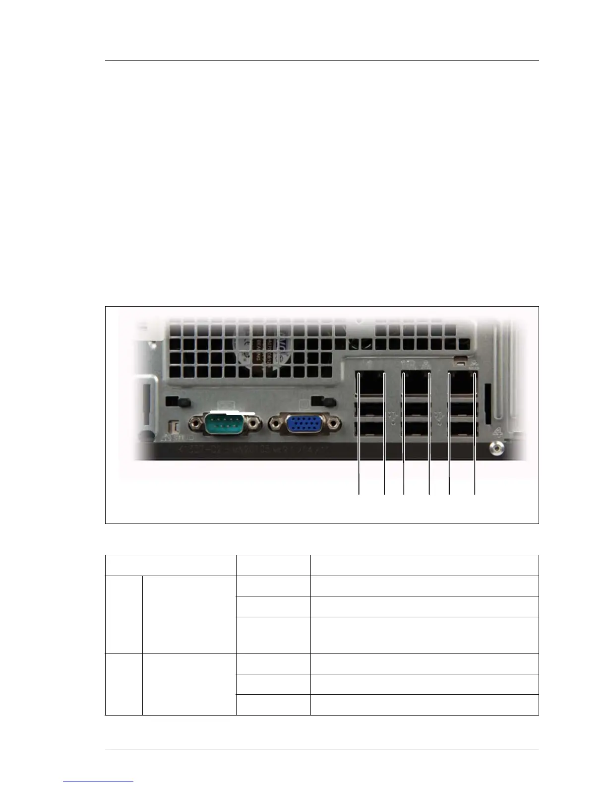
16.3.1.5 I/O panel indicators
Figure 285: Indicators on the connector panel: LAN indicators
Indicator Status Description
1
LAN
link/transfer
green on LAN connection established
off no LAN connection
green
flashing
data transfer in progress
2 LAN speed
yellow on traffic a transfer rate of 1 Gbit/s
green on traffic a transfer rate of 100 Mbit/s
off traffic a transfer rate of 10 Mbit/s
/ 0 / 0 / 0
 Loading...