Optimizing Spectral Doppler
LOGIQ 7 Online Help 5-93
Direction 2392536-100 Rev. 1
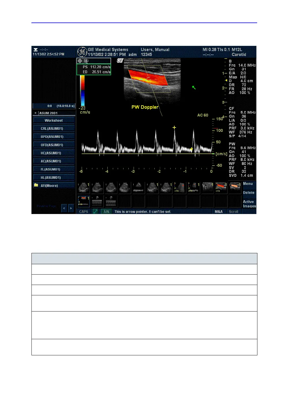
Doppler Mode Display
Figure 5-46. PW Doppler Mode Display
Table 5-6: Doppler Mode Display Explanations
Doppler Display Description, Format, Values
PRF Pulse repetition frequency, displayed as PRF in kHz.
Wall Filter Wall filter size, displayed as WF in Hz.
Doppler Gain* Displays asGN in decibels (db).
Sample Volume
Depth
Displays (in Cm) when Doppler cursor is present.
Doppler Angle
(AC ##)
Indicates angle in degrees between the Doppler mode cursor and the angle
correction indicator. Displays when Doppler cursor is present. The Doppler
Angledisplays in red when the angle exceeds 60°. Velocities obtained when the
angle is greater than 80° are displayed as asterisks (***).
Spectral Invert INVERT appears when the spectral trace is inverted and the plus/minus signs (+/-)
are reversed.

 Loading...


