Chapter 8 Mandatory Setting for Motor Drive and Test Run
8-1-8
According to the setting of "Electronic thermal subtraction function selection [b910]", the mode
in which the motor/inverter common electronic thermal operates and the mode in which the
motor electronic thermal and the inverter electronic thermal operate independently can be
selected. When "Electronic thermal subtraction function selection [b910]" ≠ 00, refer to
"Changing heat dissipation characteristics of electronic thermal" in this section.
If a current exceeding the set value
continues to flow, protection is
applied and an "overload error
[E05]" occurs.
(0.20 to 1.00) ×
Normal duty/Low duty rated
current (A)
Electronic thermal
decrease function
enable
Set the accumulated value
subtraction function of the motor
electronic thermal. When other
than "Disable (00)" is selected, the
electronic thermal for the motor
and the electronic thermal for the
inverter operate independently.
00 (Disable)/
01 (Enable: fixed subtraction
rate)/
02 (Enable: [b911] subtraction
rate)/
03 (Enable: [b912] time
constant subtraction)
Electron thermal operation
mode
Time-limited
characteristic
Common
electronic
thermal for
motor and
inverter
Separate
characteristics
for normal
duty/low duty
Electronic
thermal for
motor
Characteristics
based on
normal duty
Calculate the
accumulated load
ratio from [b012]
*1
and [b913].
Electronic
thermal for
inverter
Separate
characteristics
for normal
duty/low duty
Rated output
current of the
inverter in normal
duty/ low duty
Constant torque
characteristics
*1. "2nd-motor control [SET]" target parameter. The second control parameter is also subject to setting.
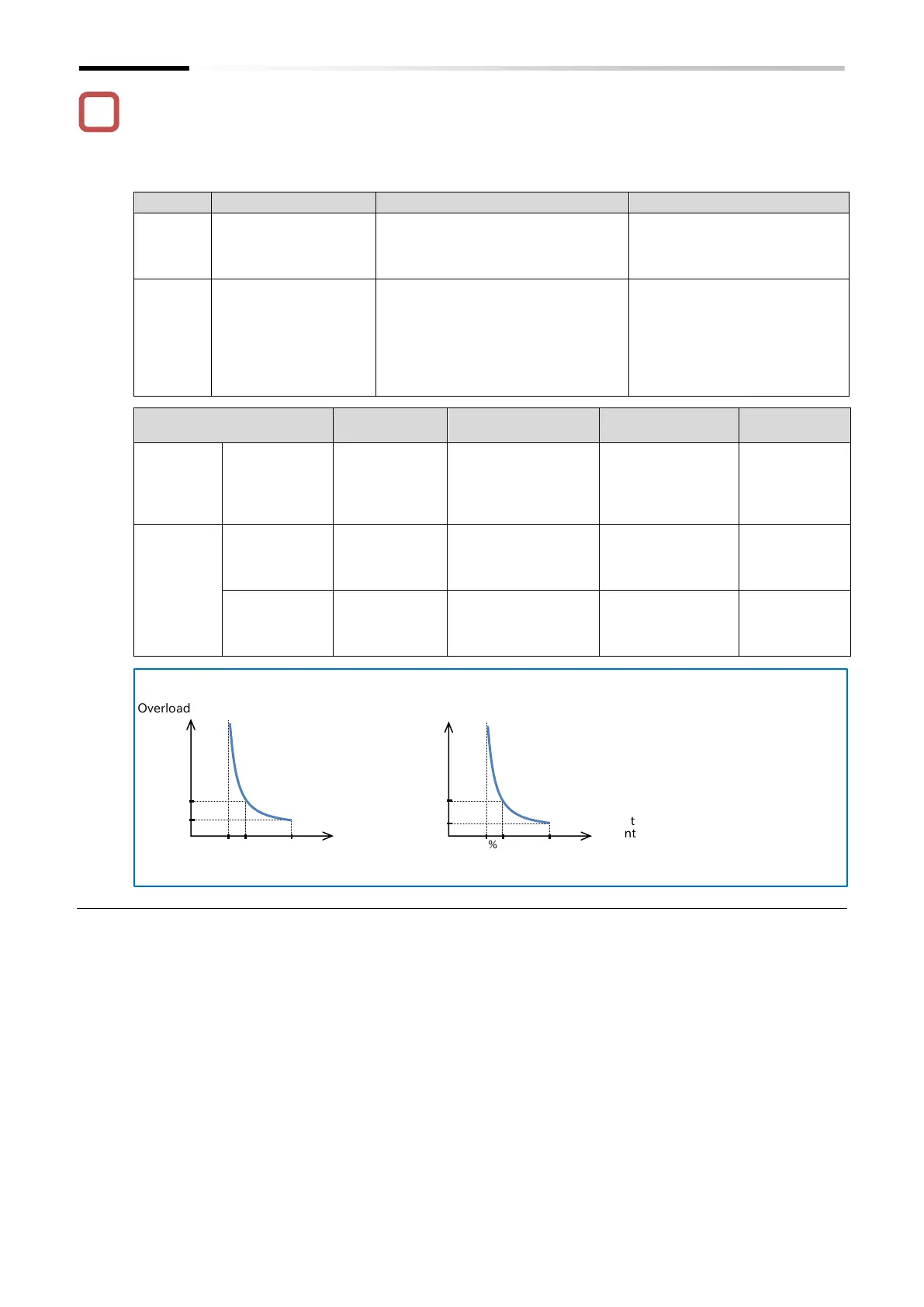
Electron thermal level ratio
● Thermal characteristics at normal duty
Electron thermal level ratio
● Thermal characteristics at low duty
(Note) The electronic thermal time
limit characteristics change as
shown in the figure on the left
in normal duty/low duty mode
setting.
・Overload rated current:
Normal duty : 150%/1 min,

 Loading...


