Chapter 5 Wire Connection
5-3-1
5.3 Applicable Peripheral Device
5.3.1 Overview of Applicable Peripheral Devices
Cautions
The applicable devices shown in this chapter are those when Hitachi standard 3-phase 4-
pole induction motor is used.
For the circuit breaker, choose an appropriate device by taking breaking capacity into
consideration. (Use an inverter-compatible type.)
To ensure safety, use an earth-leakage breaker (ELB).
Use a 60°C or 75°C copper wire (HIV wire).
(Refer to "1.4.1 UL Cautions" for details.)
If the wiring length exceeds 20 m, a thick power line needs to be used.
Use 0.75 mm2 wire for relay output terminals.
Tighten the terminal screws at specified torques. Loose tightening may cause a short circuit
or fire. Excessive tightening may damage the terminal block or inverter.
Employ different sensitive currents for earth-leakage breaker (ELB) depending on the total
wiring length between the inverter and the power supply and between the inverter and the
motor. Also, use an inverter-compatible type earth-leakage breaker. High-speed type
products may malfunction.
Leakage current is approx. 30 mA/km when CV wire is used and wired with a metal tube.
As relative permittivity of IV wire is high, the current
increases by about 8 times.
Therefore, use an item with 8 times sensitive current
that is shown on the table right.
If the total wiring length exceeds 100 m, use a CV wire.
Refer to "5.3.2 Recommended Wire Diameters, Wiring Equipment
and Crimp Terminal".
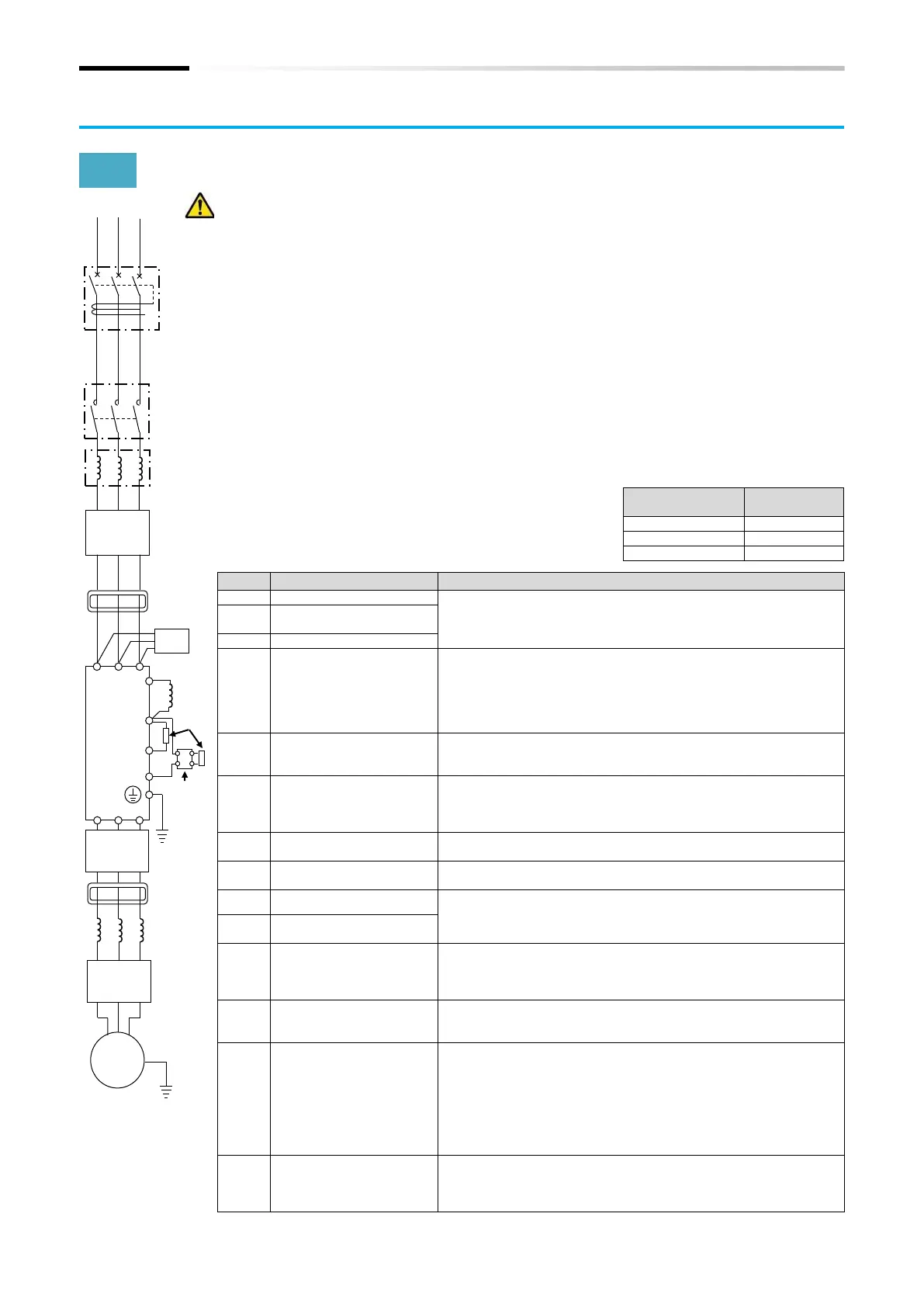
Earth-leakage breaker
(ELB)
Input-side AC reactor
(for harmonic
suppression, power
coordination, power
factor improvement)
(ALI-***)
This is applied as a countermeasure against harmonic suppression,
or when imbalance of power supply voltage is 3% or above, or
when power supply capacity is 500 kVA or above. It is also used
when a rapid change is made to power supply voltage. It is also
effective in improving power factor.
Inverter noise filter
(NF-***)
This reduces conducted noise generated from the inverter and
transmitted through the wires. Connected to the primary side
(input side) of the inverter.
Radio noise filter
(Zero-phase reactor)
(ZCL-*)
When the inverter is used, noise may be generated on an adjacent
radio or other devices through wiring on the primary side (input
side) of inverter. This is used for reducing the noise (reducing
radiation noise).
Input-side radio noise
filter (CFI-*)
This reduces the radiation noise that is emitted from the wire on
the input side.
This suppresses harmonics generated from the inverter.
This is used for increasing the braking torque of inverter, repeating
power on and off at high interval, or reducing the speed of high
load caused by moment of inertia.
Regenerative braking unit
(BRD-**)
Output-side noise filter
(ACF-C*)
This is installed between the inverter and motor to reduce the
radiation noise that is emitted from the wire. It is used to reduce
radio interference on radios or televisions or prevent
malfunctioning of measurement instruments and sensors.
Radio noise filter
(Zero-phase reactor)
(ZCL-***)
This is applied for reducing noise generated on the output side of
inverter. (It can be used on both input side and output side.)
Output-side AC reactor
(ACL-*-**)
for reducing
vibration/preventing
malfunctioning of thermal
relay
When a general-use motor is driven by the inverter, compared with
when it is run by commercial power supply, larger vibration may be
generated. By connecting this device between the inverter and
motor, the vibration of motor can be reduced. Also, if the wiring
length between the inverter and motor is long (10 m or longer), by
inserting a reactor, malfunctioning of the thermal relay caused by
harmonic attributable to switching of inverter can be prevented. It
is also possible to use a current sensor instead of a thermal relay.
This is an output-side sinusoidal filter to be installed between the
inverter and motor to improve output current and voltage
waveform to reduce motor vibration, noise, and radiation noise
from wires. It is also effective in suppressing surge voltage.

 Loading...


