Chapter 14 Safety Function STO
14-1-1
14.1 Using the Safety Function STO
(Safe Torque Off)
14.1.1 STO Function
How to use the safety function defined in the functional safety IEC61800-5-2?
The WJ-C1 is equipped with a STO (Safe Torque Off) function defined in IEC61800-5-2. This
function is equivalent to stop category 0 defined in IEC60204-1.
STO function is enabled by turning on the WJ-C1 and starting the inverter. Special operations
such as switches are not required.
IEC 61800-5-2:2016,
EN61800-5-2:2017
Diagnostic software class 1
Wiring and operation procedure of safety function
Input of STO signal is performed by redundant input of STO terminals [ST1] and [ST2]. When
voltage is applied to each input terminal and current flows, operation of safety path is enabled.
(When shipped from the factory, operation is always enabled with a short-circuit wire.)
The voltage for inputting STO signal can be selected from the inverter's internal power supply
([P24S] terminal) or an external 24 VDC power supply.
STO function is enabled and the output to the motor is shut off by turning OFF either of the
external switches for STO signal input as shown in the wiring diagram on the next page.
*1. Follow Digital input type 1 defined in IEC61131-2
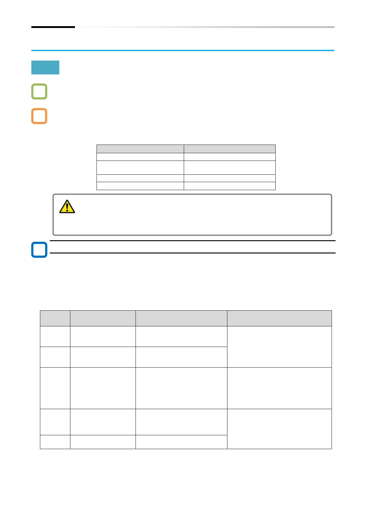
Electrical characteristics
24 VDC output
terminal
(Only for STO input)
24 VDC power supply for
contact signals dedicated to
[ST1]/[ST2] terminals.
Max. output current: 100 mA
Common for 24 VDC
output terminal
(Only for STO input)
Common terminal for [P24S].
Input terminal of STO signal.
Voltage between [ST1]/[ST2] and [CMS]:
ON Voltage: Min.15 VDC
OFF Voltage: Max.5 VDC
Maximum allowable voltage: 27 VDC
Load current: 5.8 mA (at 27 VDC)
Internal resistance: 4.7 kΩ
*1
Output terminal [11]
function
When EDM switch is turned ON,
output terminal [11] becomes
STO state monitor output (EDM
signal).
Open collector output
Between [11] and [CM2]
Voltage drop at ON: 4 VDC or less
Maximum allowable voltage: 27 VDC
Maximum allowable current: 50 mA
Common for output
terminal
Common terminal for output
terminal [11].
This guide explains only the outline of the STO function. When this product is
handled as a functional safety certified product, be sure to check the separate "WJ
Series C1 Safety Function Guide (NT3612*X)" and implement the items required as
a functional safety system (verification, validation, etc.).
The information given in WJ Series C1 Safety Function Guide takes precedence.

 Loading...


