Chapter 9 Inverter Functions
9-16-5
9.16.3 Outputting Monitor Data by Pulse Output
How to output the inverter monitor data externally by pulse output?
How to acquire data with the digital frequency counter?
The digital output function allows monitored values such as output frequency and output
current to be output from the [Ao2] terminal by PWM output or pulse output.
Use the digital frequency counter to monitor pulse output data. For other output signals, use the
analog meter.
Pulse output cannot exceed the maximum output range (32 kHz) of the [Ao2] terminal.
[Ao2] Output monitor selection
Selects data to be output from the [Ao2]
terminal.
List of [Ao2] terminal output data ([C027] set values)
The following lists the data that can be output from the [Ao2] terminal.
0 to the maximum frequency (Hz)
Digital output frequency
*4
0 to the maximum frequency (Hz)
0 to 133 (%)
(e.g., Duty ratio : approx. 0.75 at 200 V in 200 V class)
Electronic thermal load
ratio
0 to the maximum frequency (Hz)
Sets the output current for the [C030] setting to 1,440 Hz.
0 to 200 (°C) (0 output for temperatures below 0°C)
General-purpose analog
YA(0)
*5
- (currently no supported options)
*1. "LAD frequency" is the frequency commanded by the inverter and corresponds to "Output frequency
monitor [d001]". "Output frequency (00)" is a value that takes into account vector control compensation
and stabilization control such as sensorless vector control. "Output frequency" output may appear
unstable at low speeds during overload limit deceleration, etc. In this case, changing it to "LAD
frequency" results in a better stability.
*2. When "Speed feedback" is set for "Pulse input, target function selection [P003]", "detect speed monitor
[d008]" is outputted.
*3. Valid only when the control method is sensorless vector control.
*4. When "Frequency conversion gain [b086]" is set, a converted value is outputted for the digital output
frequency.
*5. For details on YA(0), refer to the "Easy-Sequence Function (EzSQ) Programming Guide (NT2021*X)".
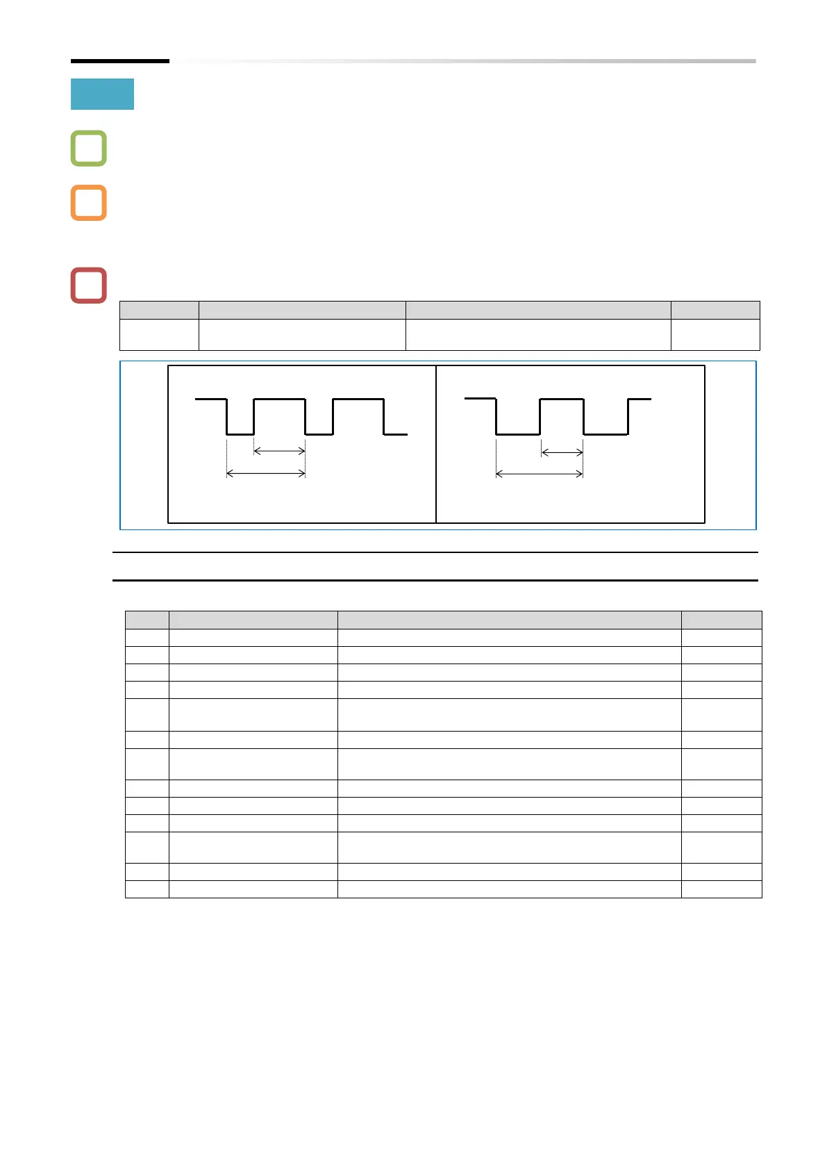
Cycle T: Constant (6.4 ms)
Duty ratio t/T: Variable
Cycle T: Variable
Duty ratio t/T: T/2 (Fixed)

 Loading...


