Chapter 11 RS485 Communication
11-1-5
11.1.4 Message Configuration
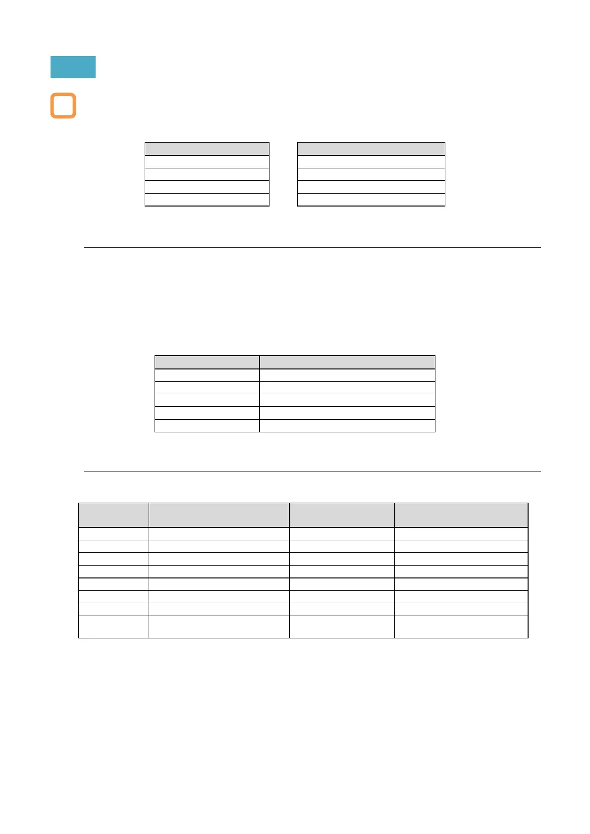
The command message sent from the master to the slave is called "Query", and the response
message from the slave is called "Response". The transmission format of "Query" and "Response"
is shown below.
Slave address for checking
Function code for checking
■ (1) Slave address (communication node address)
The slave address is a number in the range of 1 to 247 set in advance for each inverter (slave).
(The query is fetched only by the inverter that matches the slave address of the query.)
If "0" is specified as the slave address of the destination on the master side, broadcast to all
stations can be performed. For broadcast, all slaves receive data, but do not return a response.
During broadcast, data cannot be read or looped back.
In Modbus specification, the slave address is 1 to 247. However, if slave addresses 250 to 254
are used on the master side, broadcasting can be performed only for a specific slave address.
(Slaves do not respond, and broadcast is valid only for write commands (05h, 06h, 0Fh, 10h).)
Broadcast to slave addresses 01 to 09
Broadcast to slave addresses 10 to 19
Broadcast to slave addresses 20 to 29
Broadcast to slave addresses 30 to 39
Broadcast to slave addresses 40 to 247
■ (2) Function code
The function executed by the inverter is specified by the function code.
The corresponding function code is shown below.
Max. data bytes
handled by 1 massage
Max. number of data
handled by 1 message
Read/write multiple holding
registers
16/16 registers (in bytes)

 Loading...


