Chapter 9 Inverter Functions
9-9-8
9.9.5 Suppressing Overvoltage with Braking Resistor
How to avoid overvoltage errors when decelerating the motor?
How to avoid overvoltage errors due to a regenerative load?
How to drive the motor in a quick deceleration application?
How to avoid overvoltage errors during the lowering operation?
During deceleration, the motor acts as a generator and energy is regenerated to the inverter. As
a result, the P-N voltage rises and the inverter trips when the overvoltage level is exceeded. To
prevent this, the BRD function uses external resistors to consume the regenerative energy from
the motor as heat.
To use this function, connect external braking resistors and set each parameter in the table
below based on "5.3.5 Wiring of Braking Resistor and Regenerative Braking Unit".
Instead of using the built-in braking resistor operation circuit (BRD), an optional regenerative
braking unit can be used to obtain greater regenerative torque. In this case, set "Dynamic brake
activation selection [b095]" to "Disable (00)".
The "Dynamic brake activation level [b096]" is the level specified in the main circuit DC
smoothing capacitor within the inverter. Be sure to set a value that exceeds √2 times the input
voltage. Otherwise, the braking resistors may burnout.
The minimum resistance value that can be connected depends on the model. For details, refer
to "Chapter 17 Specifications/Dimensions/Derating".
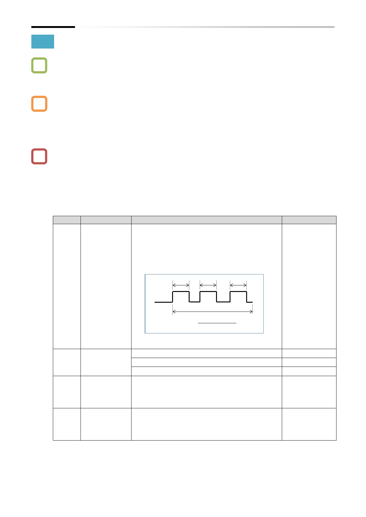
When this setting is 0.0, the BRD function is not
activated.
The upper limit value of [b090] varies depending on the
setting of "Dynamic brake resistor value [b097]". Be
sure to set the [b097] value first. Then, set the BRD use
ratio to a value equal to or less than the allowable % ED
of the braking resistor to be connected, based on the
drawing below.
When the specified use rate is exceeded, the inverter
trips with "Braking resistor overload error [E06]".
This is the level the BRD function is activated. This
value is used to adjust the operation level of the BRD
function that corresponds to the input voltage of the
inverter. Be sure to set a value that exceeds √2 times
the input voltage.
Set the resistance value of the actually connected BRD
resistor. The upper limit value of the BRD use rate for
the inverter will be automatically calculated. This
means that only the allowable % ED of the BRD resistor
needs to be considered when setting [b090].

 Loading...


