Chapter 9 Inverter Functions
9-16-1
9.16 Functions with External Signal Output
9.16.1 Using External I/O Output Signal Functions
How to detect warning, error, and status signals emitted by the inverter with an external system?
Output terminals [11], [12], [AL0]-[AL1]/[AL0]-[AL2] are intelligent output terminals. By assigning
the functions in the list of output terminal functions shown on the next page to [C021], [C022],
and [C026], the specified functions can be assigned to the corresponding output terminals.
The output terminals [11], [12], [AL0]-[AL1]/[AL0]-[AL2] can be individually selected as "a"
contact (NO) input or "b" contact (NC) input by setting [C031], [C032], and [C036].
The output terminals [11] and [12] are open collector outputs, and the output terminals [AL0]-
[AL1]/[AL0]-[AL2] are "c" contact relay outputs.
When using a "c" contact relay, check the power supply status and the open/close status of the
relay output terminals.
Assigns output terminal functions to the output
terminals [11], [12], [AL0] to [AL1]/[AL0] to [AL2].
The settings of [C021], [C022], and [C026]
correspond to the output terminals, respectively.
Refer to the list of
output terminal
functions on the next
page.
Output terminal
active state
Operates as "a" contact (NO).
Operates as "b" contact (NC).
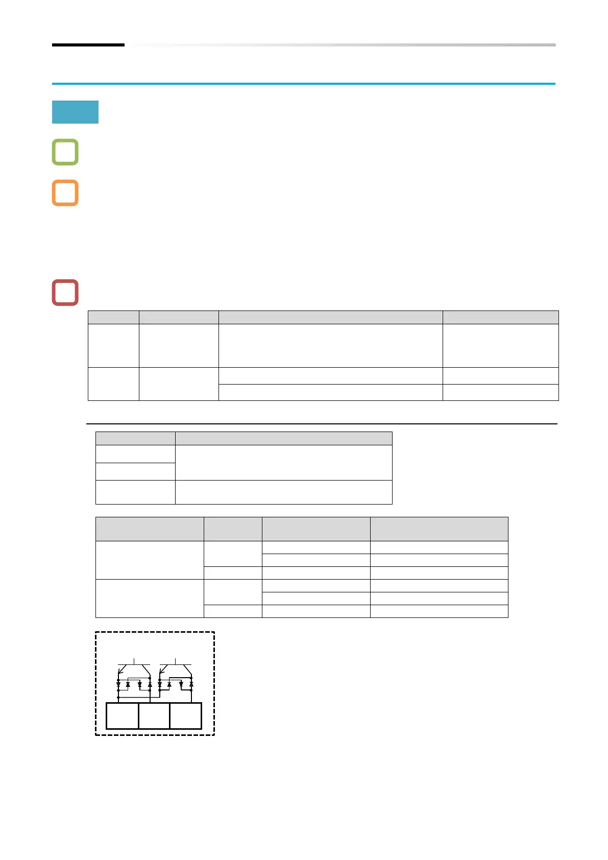
■ Open collector output terminal specifications
Electrical characteristics
Voltage decreases when ON: 4 VDC or less
Allowable maximum voltage: 27 VDC
Allowable maximum current: 50 mA
Common terminal of [11] and [12]
Allowable maximum current: 100 mA
Output terminal active
state
Open collector output
terminal (inside the inverter)
* Terminal names such as [FW] under the
terminal numbers are initial assigned
functions when "Initialize data selection
[b085]" set to "Pattern 0 (00)". For details
of initial setting when [b085] is set to
other value, refer to "18.2.5 C Parameter
Group".

 Loading...


