Chapter 9 Inverter Functions
9-11-1
9.11 Outputting Warning Signals to Terminals
9.11.1 Outputting an Alarm Signal
How to detect an error condition in the inverter and inform the system?
Assigning an "Alarm [AL] (05)" to one of the output terminal functions ([C021]/[C022]/[C026])
will output an alarm signal when the inverter trips.
Output terminal active state ([C031]/[C032]/[C036]) allows you to individually set contact a
(NO: Normally Open) or contact b (NC: Normally Close) output specifications to the output
terminals [11]/[12] and the relay output terminals [AL1]-[AL0]/[AL2]-[AL0].
In the initial state, the "Alarm [AL] (05)" signal is assigned to the contact c relay of [AL1]-[AL0]/
[AL2]-[AL0].
- "Output terminal [AL] function [C026]" = "Alarm [AL] (05)"
- "Output terminal [AL] active state [C036]" = "NC: Normally Closed (01)"
If the system recognizes an error during the inverter power interruption, changing the wiring and
selecting different contact point may improve the situation.
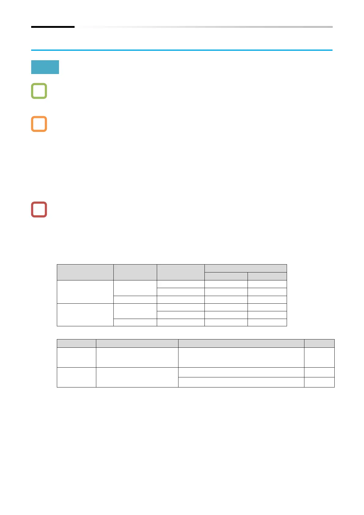
In the factory default state, [AL2]-[AL0] is "close" when the power is turned off, and "open" when
the power is turned on and there is no error in the inverter, as shown in the table below. To
avoid this condition, set "Output terminal [AL] active state (C036)" to "NO: Noramlly Open (00)"
or change the wire where the error was detected.
For electrical specifications of the relay contacts [AL1]-[AL0]/ [AL2]-[AL0], refer to "5.4 Control
Circuit Terminal".

 Loading...


