Chapter 9 Inverter Functions
9-11-3
9.11.3 Outputting a Warning When Overload Occurs
How to be notified of the increase in the motor output current by a warning signal?
How to be notified of the increase in motor current as soon as possible?
Assigning an "Overload warning notice [OL] (03)" or "Overload warning notice 2 [OL2] (26)" to
one of the output terminal functions ([C021]/[C022]/[C026]) enables the inverter to output an
overload warning signal.
The overload warning signal is output when the output current exceeds the overload warning
level.
By changing the "Overload signal output mode selection [C040]", the signal can be output
according to the operating status.
If the overload warning level is set too high, an overcurrent error may occur before the overload
warning signal is output. In this case, lower the overload warning level.
When an analog input is used for the output frequency command input source, the frequency
command input may not be determined as constant speed due to fine fluctuations in the
frequency input. In this case, change the "Overload signal output mode selection [C040]" to
"Enable during running (00)" or increase the "Analog input filter time constant [A016]".
Sets the filter that acts on the [OL], [OL2],
and [LOC] detection levels.
Overload warning notice [OL]:
This signal turns on when the output
current exceeds the overload warning level.
Overload warning notice 2 [OL2]:
This signal turns on when the output
current exceeds the overload warning
level 2.
*1. Parameter for "Second Control [SET]". ting also applies to the second control parameter.
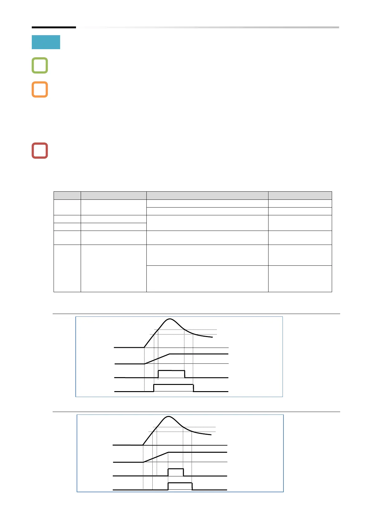
■ When [C040] is set to "Enable during running (00)"
■ When [C040] is set to "Enable only during constant speed (01)"

 Loading...


