Chapter 3 Main Body of the Product
3-2-4
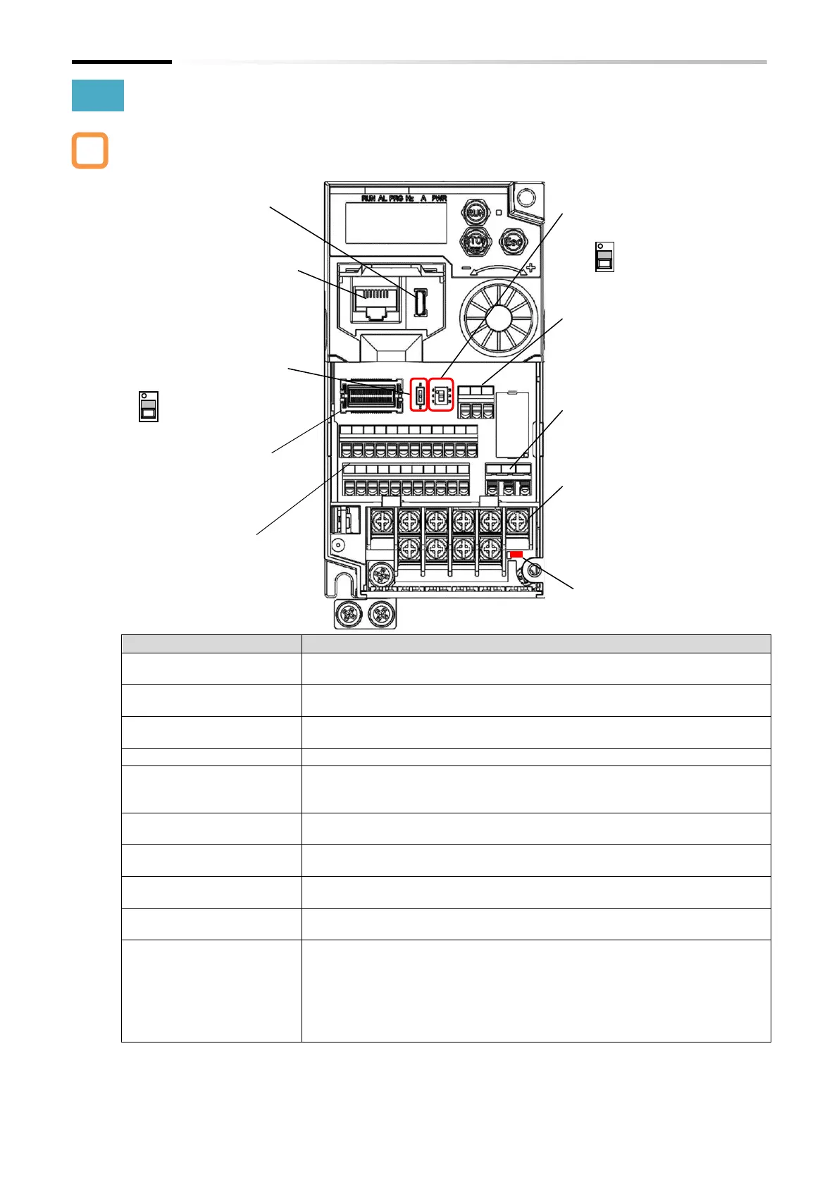
3.2.2 Part Names and Descriptions on the Front of the Product
The appearance from the front of the product without the terminal cover and the names of the
parts are shown below.
USB connector (Micro-B) for connecting to a PC. (Only when inverter
configuration software ProDriveNext and EzSQ function are used.)
(2) RJ45 connector for
remote operator
Connector for connecting the optional external remote operator (OPE-SR,
OPE-SBK, OPE-SRmini, WOP).
(3) Termination resistor
switch
Termination resister switch for the RS485 communication terminal on the
control terminal. When turned on, the built-in resistor (120Ω) is connected.
(4) Option board connector
Connector for mounting option board.
Turn ON in case of using the EDM output of the safety function.
Be sure to turn off the power before switching ON/OFF. (Refer to section
14.1.2.)
(6) Safety function STO input
1/2
Terminal block for input signals of safety function. (Refer to section 14.1.1.)
(7) Control circuit terminal
Terminal block for connecting various digital/analog input/output signals for
inverter control.
(8) Intelligent relay output
terminal
1c contact terminal block for intelligent relay output.
(9) Main circuit terminal
Terminal block for connecting the inverter main power supply, motor output,
braking resistor, etc.
(10) Charge lamp (Charging
indicator lamp)
This lamp lights when the main circuit DC voltage (between [P/+] terminal
and [N/-] terminal) is approximately 45 VDC or more even after the power
supply is shut off. The voltage does not necessarily run out even if the charge
lamp goes off. When changing the wiring, wait for 10 minutes or more after
shutting off the power, and check that there is no residual voltage between
[P/+] and [N/-] terminals by using a tester or other instrument to confirm
safety.
* Refer to "7.1 How to Use Keypad" for the displays and keys on the keypad.
* The position of the (10) charge lamp depends on the model. Refer to "5.2.3 Arrangement of Main Circuit
Terminal Block" for the positions of each model.
* Please note that operation is also possible from the inverter main unit when driving from a PC via USB.
* Disconnect the power supply before connecting or disconnecting the remote operator (OPE-SRmini, etc.)
to or from the (2) RJ45 connector for remote operator.
⇒ "14.1.2 STO State Monitor
Output (EDM Signal)"
(1) USB connector (Micro-B)
(4) Option board connector
"Chapter 13 Option Board"
(8) Intelligent relay output terminal
"5.4 Control Circuit Terminal"
(2) RJ45 connector for remote operator
⇒"3.2.3 Connecting Remote
Operator"
(7) Control circuit terminal
⇒"5.4 Control Circuit Terminal"
(6) Safety function STO input 1/2
(9) Main circuit terminal
"5.2 Main Circuit Terminal"
(3) Termination resistor switch

 Loading...


