Chapter 9 Inverter Functions
9-5-8
9.5.5 Driving with V/f Control with Encoder
How to use speed feedback from the motor to apply V/f control with a high degree of rotational
accuracy?
How to closely control fan and pump rotational output based on their speed characteristics?
How to accurately make motor rotation follow the frequency command in order to calculate the
number of turns?
The V/f control with encoder function is a function that uses an encoder to provide feedback of
the motor's actual speed for highly accurate frequency control.
This function controls the motor by correcting PI control so that the number of motor rotations
follows the frequency command.
The V/f control with encoder function is unavailable when "2nd-motor control [SET]" is ON. This
function is only available when using the first control mode.
To set "90 degrees shift pulse (01)" or "Forward and reverse command and pulse (03)" for "Pulse
input mode selection [P004]", set "Input terminal [7] function [C007]" to "Pulse input B [PLB]
(85)". [PLB] can only be assigned to input terminal [7], and the active state (NO/NC) settings will
also be disabled.
For details on encoders, refer to "9.5.8 Using Encoder Feedback".
V/f control with encoder is only available when
using V/f control of first control mode.
Pulse input, target function
selection
Pulse input mode selection
90° phase difference pulse input
Forward/reverse rotation command and pulse input
Sets the number of pulses per encoder revolution.
Simple positioning selection
Simple position control disabled
Over-speed detection level
If [P003] is 01 and [P026] is a value other than 0.0, an
"Over-speed error [E81]" trip will occur when the
"Detect speed monitor [d008]" equals or exceeds the
{Maximum frequency × [P026]} during operation.
Speed deviation error
detection level
Sets the excessive speed deviation level when an
"Speed over deviation [DSE]" is assigned to "Output
terminal function ([C021] to [C026])".
Speed detection filter
constant for encoder pulse
Filter time constant for the detected speed by
encoder pulse input.
Slip compensation P-gain
at V/f with encoder
Proportional (P) gain for slip compensation when
using V/f control with encoder.
Slip compensation I-gain at
V/f with encoder
Integral (I) gain for slip compensation when using
V/f control with encoder. Set using integral time.
Input terminal [7] function
Pulse input B [PLB]:
The [PLB] terminal is the input terminal for the
direction signal or phase B pulse input during
encoder feedback.
Speed over deviation [DSE]:
The [DSE] signal turns on when the following
conditions are met during operation.
| [d001] - [d008] | ≧ [P027]
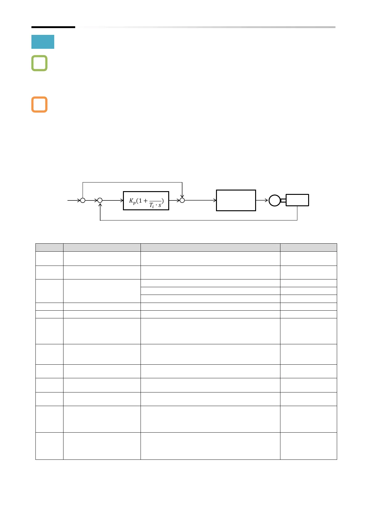
Kp: Proportional gain setting, Ti: Integral time, s: Operator, ε: Deviation
Ki: Integral gain setting (Ki=Kp/Ti)

 Loading...


