Chapter 11 RS485 Communication
11-1-3
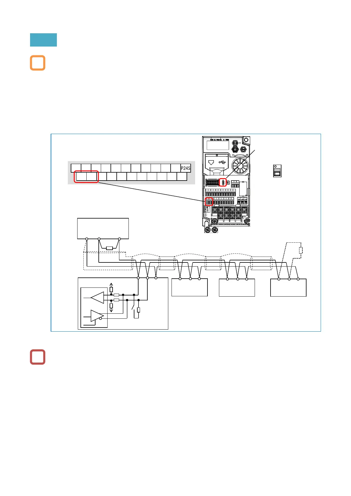
11.1.2 Communication Wiring and Connection
The figure below shows an example of wiring for RS-485 communication. When multiple
inverters are connected, each inverter is connected in parallel.
For the communication cable, use a twisted pair cable for communication and a 3-wire shielded
cable for ground connection. Connect the signal ground (SG) of the external control equipment
to the [L] terminal of the inverter.
Install a termination resistor that matches the characteristic impedance of the cable at both
ends of the communication cable. When WJ-C1 is connected at end communication line, turn
on the termination resistor switch. When performing RS-485 communication with a single
inverter, turn on the termination resistor switch of that inverter. (The built-in termination resistor
of WJ-C1 is 120 Ω.)
Communication is possible only with a 2-core twisted pair cable, but it is not recommended
because communication may become unstable due to noise.
Communication cables should be separated from high voltage circuits such as power lines and
alarm relay wiring, and should not be laid in parallel.
Communication may become unstable depending on the operating environment of the inverter,
the cables used for communication lines, and the wiring conditions. In this case, perform the
following.
- Check whether the termination resistor is connected to both ends of the communication
cable. Or use a termination resistor that matches the characteristic impedance of the cable.
- Check the connection between the signal ground (SG) of the external control equipment
(master) and [L] terminal of each inverter.
- Normally, the shield of the wire should be grounded at one point to the SG of the external
control equipment. Or, change the grounding method of the shield while checking that the
communication is stable. (For example, ground to the L terminal of any inverter, do not
perform shield grounding, etc.)
- If the communication distance is long (100 m or more), reduce the baud rate or insert a
repeater.

 Loading...


