Chapter 9 Inverter Functions
9-7-16
9.7.10 Starting and Stopping with External Brake Control
How to perform a sequence of operations using an external brake?
The brake control function gives the inverter control over external brakes used for elevator
systems, etc. When using this function, set "Brake control enable [b120]" to "Enable (01)", and
assign "Brake release [BRK] (19)" to the output terminal.
When operating this function while interlocking by inputting an engagement/release check
signal from an external brake to the inverter, assign "Answer back from brake [BOK] (44)" to the
input terminal and set "Brake confirmation signal wait time [b124]". If necessary, assign "Brake
error [BER] (20)" to the output terminal.
The brake control function can also be used in combination with simple position control. For
details, refer to "9.14.4 Operating Simple Position Control with Brake Control".
Sensorless vector control is the recommended control method when using the brake control
function, as this generates high torque at startup.
If an error occurs in the brake sequence, the inverter trips with "Brake error [E36]", and turns on
"Brake error [BER] (20)". For details on tripping conditions, refer to the sequence of operations
described below.
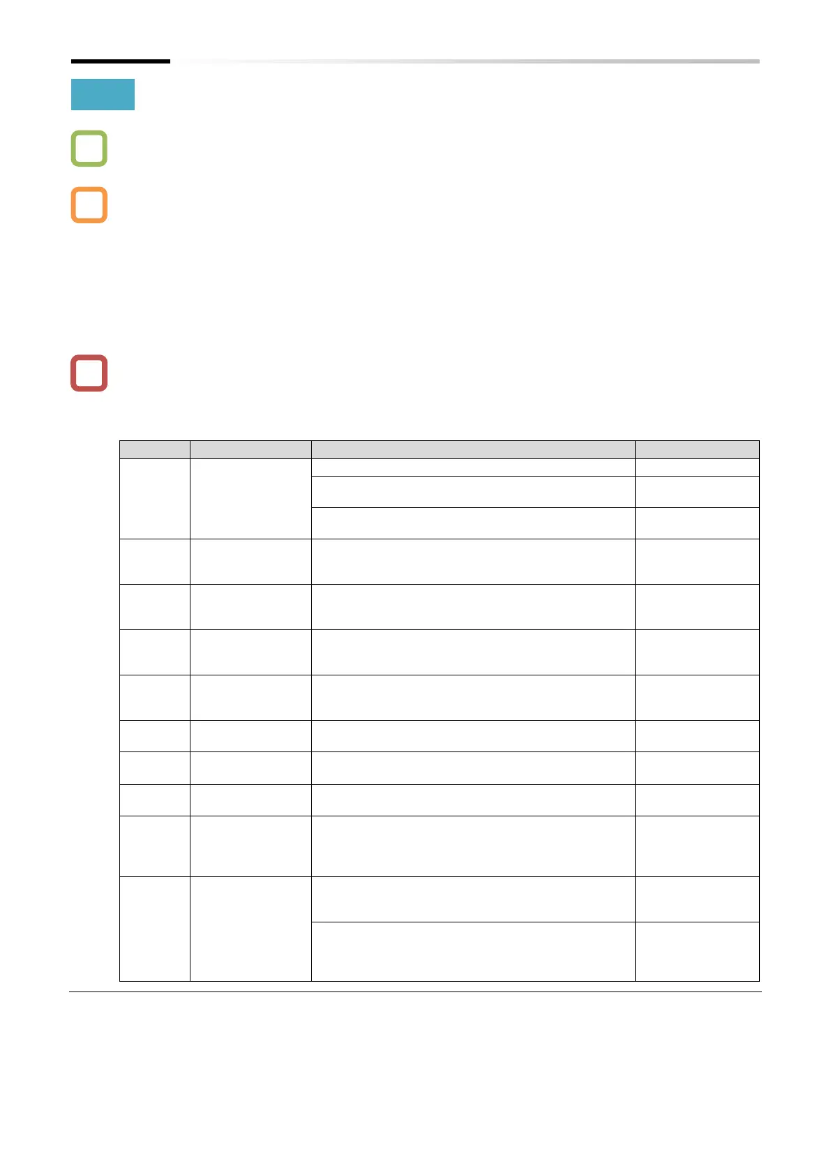
Enabled (DC braking enabled at stop when position
control is enabled)
Enabled (DC braking disabled at stop when position
control is enabled)
Sets the time required for the output current to
reach the brake release current after the brake
release frequency is reached.
Brake wait time
for accel.
Sets the mechanical delay time from the brake
confirmation signal (or the brake release signal) is
received until the brake is released.
Brake wait time
for stopping
Sets the mechanical delay time from the brake
release signal is turned off until the brake is
engaged.
Brake
confirmation
signal wait time
Sets the time or longer from the brake release signal
is output until the release completion signal output
from the brake is received by the inverter.
Brake release
frequency
*1
Sets the frequency at which the brake release signal
is turned on.
Sets the output current at which the brake release is
permitted.
(0.0 to 2.0) ×
rated current (A)
Sets the frequency at which the brake is closed
when stopping.
Answer back from brake [BOK]:
This checks the input signal using the answer
returned for the [BRK] output signal to the external
brake.
Brake release [BRK]:
It is the signal for an external brake
engagement/release.
Brake error [BER]:
Turns on in the event of a sequence error for the
brake control function. When this signal is turned
on, the inverter trips with the "Brake error [E36]".
*1. Set this to a value greater than the "Minimum frequency [b082]".
*2. Note that a lower value may not produce sufficient torque when the brake is released.

 Loading...


