Chapter 9 Inverter Functions
9-2-1
9.2 Selecting Frequency Command
9.2.1 Types of Frequency Command
What types of frequency command input sources can be selected for the inverter and what is
their order of priority?
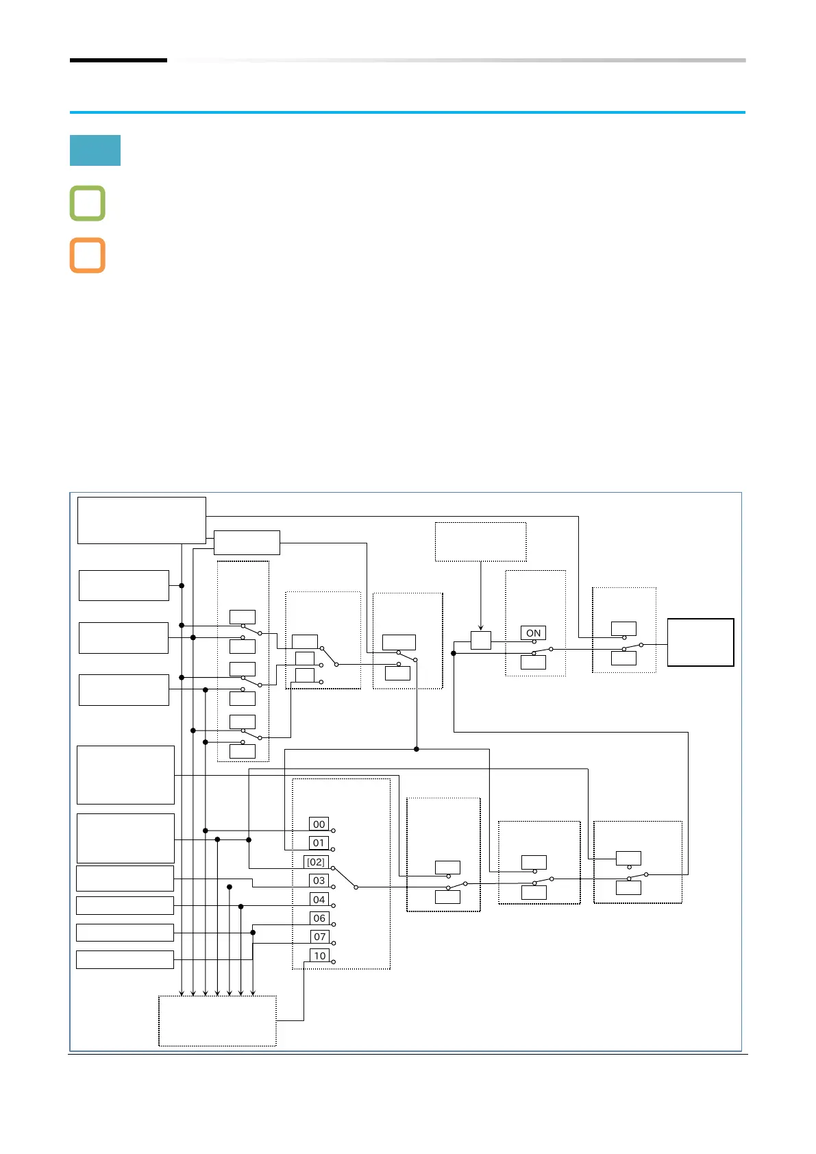
The following diagram shows the parameters and input terminal functions that affect the output
frequency command input source selection.
The command input source is set according to the "Frequency input source selection [A001]
*1
".
Please note that when multiple settings are turned on, the frequency command for each input
terminal function is selected with the following order or priority: "Multi-speed selection [CF1] to
[CF4]/[SF1] to [SF7] (02 to 05/32 to 38)", "Force terminal [F-TM] (51)", "Force operation [F-OP]
(31)" and then "Jogging [JG] (06)".
When the command input source is the first/second motor multi-speed 0, multi-speed 1 to 15,
or jogging frequency, the "Output frequency setting or motor [F001]" parameter can be used to
change the frequency command. A setting change with the [F001] also changes the value of the
selected frequency input source parameter.
(For example, if the frequency input source is set to "Multi-speed 1 [A021]", the [A021] setting is
displayed in [F001]. If [F001] is changed, this is also reflected in [A021].)
When the frequency input source is an analog input or Modbus communication, [F001] is used
to monitor the output frequency command value.
*
1. "2nd-motor control [SET]" target parameter. The second control parameter is also subject to setting.
switch positions shown in the figure
are the default values. All input
terminal functions not assigned to
input terminal function selection

 Loading...


