EasyManuals Logo

Hitachi WJ C1 Series User Manual

Hitachi WJ C1 Series
494 pages
To Next Page IconTo Next Page
To Previous Page IconTo Previous Page
Page #164 background imageLoading...
Page #164 background image
Chapter 9 Inverter Functions
9-2-13
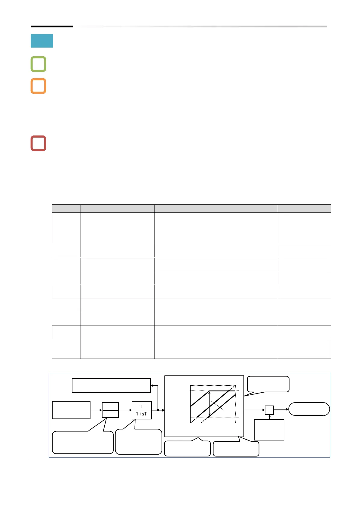
9.2.8 Setting Frequency Command by Pulse Input
 How to set the frequency command using an open collector pulse input?
 To set the output frequency command using a pulse input from the [PLA] terminal, set the
"Frequency input source selection [A001]
*1
" to "Pulse input (06)". At the same time, set the
"Pulse input, target function selection [P003]" to "Pulse input frequency command (00)" and the
"Simple positioning selection [P012]" to "Simple positioning disabled (00)".
 Set the input pulse frequency, that makes the frequency command equivalent to the "Maximum
frequency [A004]
*1
", in the "Pulse frequency scale [P055]".
 The pulse input value can be monitored using "Pulse input [PLA] monitor [d133]".
 The analog input start/end function cannot be used. To limit the pulse input frequency
command, set the "Pulse frequency bias value [P057]", the "Pulse upper frequency detection
level [P058]", and the "Pulse lower frequency detection level [P059]".
 Trying to stop the inverter by setting the pulse input frequency to 0 Hz may cause the
deceleration to stall. In such a case, turn off the RUN command to stop the inverter.
 If the pulse input frequency falls to or below the "Pulse lower frequency detection level [P059]",
it is treated as if the input is set to 0 Hz.
 If the "Pulse lower frequency detection level [P059]" setting is too high, start-up may be too
slow.
Code
Item
Description
Data
[d133]
Pulse input [PLA] monitor
Monitors the pulse frequency from the [PLA]
terminal as a percentage with [P055]
indicating a value of 100%. This monitor
continuously operates regardless of all other
settings.
0.00 to 100.00 (%)
[A001]
*1
Frequency input source
selection
Used to set the pulse input as the frequency
command input source.
06
[P003]
Pulse input, target
function selection
Used to set the pulse input as the frequency
command input source.
00
[P012]
Simple positioning
selection
Used to set the pulse input as the frequency
command input source.
00
[P055]
Pulse frequency scale
Enter the pulse frequency that is equivalent to
the maximum frequency.
1.0 to 32.0 (kHz)
[P056]
Pulse frequency filter time
constant
Filters the pulse frequency input.
0.01 to 2.00 (s)
[P057]
Pulse frequency bias
value
Applies a bias to the pulse frequency input.
-100 to 100 (%)
[P058]
Pulse upper frequency
detection level
Limits the output of the pulse frequency input.
0 to 100 (%)
[P059]
Pulse lower frequency
detection level
Sets the pulse value to 0.0% when the output
of the pulse frequency input falls to or below
the set lower limit.
0.01 to 20.00 (%)
â—¼ Pulse command frequency processing block diagram
*1. "2nd-motor control [SET]" target parameter. The second control parameter is also subject to setting.
Pulse frequency
acquisition
1+sT
1
×
Maximum
frequency
[A004]
*1
Frequency
command
Bias/Upper limit/Lower limit
Hz
%
Frequency command unit
Pulse frequency scale G
[P055] (1.0 to 32.0 kHz)
G
1
Filter time
constant T [P056]
(0.01 to 2.00 s)
%
100(%)
0(%)
100(%)
Input
Outp
ut
Upper limit [P058]
(0 to 100%)
Lower limit [P059]
(0.01 to 20.00%)
Bias [P057]
(-100 to +100%)
0(%)
[P058]
[P059]
Bias
Pulse input [PLA] monitor [d133]
(0.00 to 100.00%)
Q
A
!

Table of Contents

Questions and Answers:

Question and Answer IconNeed help?

Do you have a question about the Hitachi WJ C1 Series and is the answer not in the manual?

Hitachi WJ C1 Series Specifications

General IconGeneral
BrandHitachi
ModelWJ C1 Series
CategoryInverter
LanguageEnglish

Related product manuals