Chapter 5 Wire Connection
5-4-1
5.4 Control Circuit Terminal
5.4.1 Configuration of Control Circuit Terminal
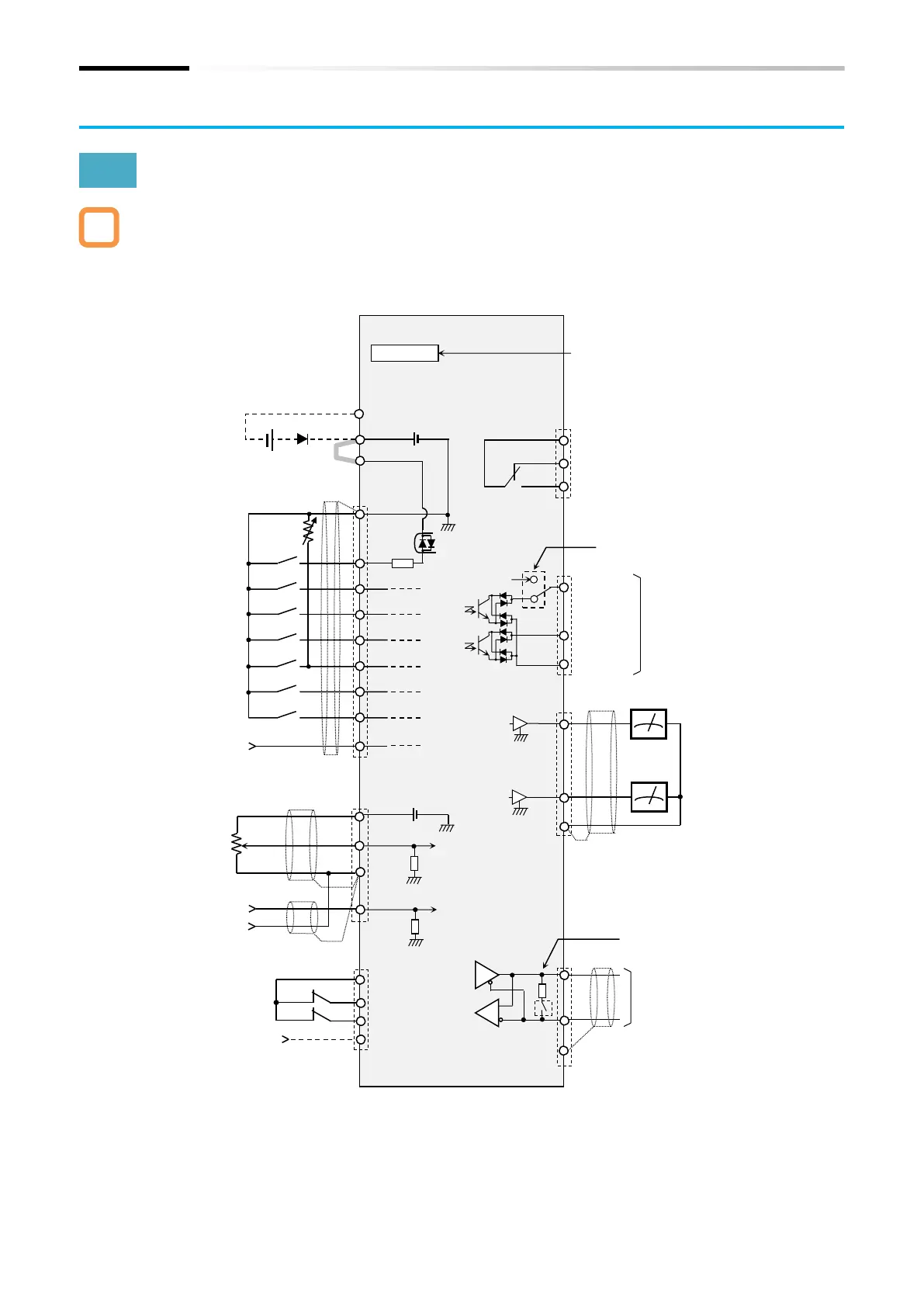
Control circuit terminal wires are shown in the figure below. Check the cautions, functions, and
electrical specifications of the control circuit terminal wiring in this section, and pay sufficient
attention to wiring so that there is no incorrect wiring.
Option board connector
(WJ200 communication option
can be installed)
*1. "Thermistor input [PTC]" can only be assigned to input terminal [5].
*2. "Pulse input B [PLB]" can only be assigned to input terminal [7].
*3. Input terminal [8] has a fixed function as the "Pulse input A [PLA]" input terminal.
*4. The electrical specifications of the A-phase and B-phase of the pulse input terminals are different.
Take care when inputting 2-phase pulse.
*5. Output terminal [11] switches to the "STO state monitor output [EDM]" by turning on the switch
Safety function
STO input 1/2
using an external
power supply for
Intelligent relay output terminal
1c contact
(0 to 10 VDC)
(0 to 10 VDC
to 7 terminals
(5 to 24 VDC Max.32 kHz,
common is L terminal)
External 24 VDC power supply
input for control circuit
(Reverse current prevention
diode is mandatory)
*Refer to "5.4.3 Switching
Sink/Source Logic and
Connecting External Power
Supply/Programmable
Controller" for details when
switching the sink/source logic
and using external devices or
external power supply.
Analog input 1
(0 to 10 VDC)
Analog input 2
(4 to 20 mA)
10 VDC power supply (Max.10 mA)
Intelligent output terminal
(open collector)
Sink/source support
Modbus-RTU, EzCOM
communication port
(RS485/Max 115.2 kbps)
Termination resistor switch (120 Ω)
Connect the signal ground of the
external communication device to L
terminal.

 Loading...


