Chapter 9 Inverter Functions
9-2-8
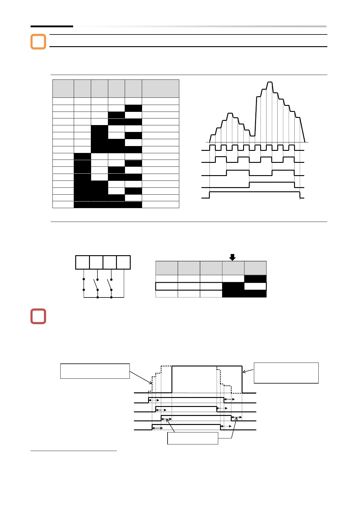
Binary operation mode (commands for up to 16 speeds: [A019] = 00)
By assigning "Multi-speed selection [CF1] to [CF4]" to "Input terminal function [C001] to [C007]",
it is possible to switch between multi-speed settings 0 to 15.
■ Binary operation mode control table
Frequency
setting
parameter
■ Example of using binary operation mode
When using binary operation, the wait time until the multi-speed level is determined can be set
with the "Multistage input determination time [C169]". This prevents the frequency command
signal from accidentally representing an incorrect speed level when switching multi-speed
terminals.
After the last rising/falling edge input to the multi-speed terminal, the multi-speed command is
determined after the [C169] set time has elapsed. Please note that increasing the determination
time results in slower input response.
*
"2nd-motor control [SET]" target parameter. The second control parameter is also subject to setting.
*
Multi-speed 0 is the frequency command set by the "Frequency input source selection [A001]
*1
" parameter.
In this example, [C006] = "Multi speed selection 1 [CF1]" and [C007] =
"Multi speed selection 2 [CF2]", while [CF3] and [CF4] are
unassigned. At this time, if only input terminal [7] ([CF2]) is
turned on, it corresponds with multi-speed 2, and "Output
Multistage input
determination time
[C169]
When the determination time
is set to zero ([C169] = 0)
When the determination
time is set to a value other
than zero ([C169] ≠ 0)

 Loading...


