Chapter 9 Inverter Functions
9-5-15
Pulse input mode and encoder connections
To set "90 degrees shift pulse (01)" or "Forward and reverse command and pulse (03)" as the
"Pulse input mode selection [P004]", set "Pulse input B [PLB] (85)" to input terminal [7]. When
doing so, the active state (NO/NC) setting is disabled. Also note that hardware specifications
different between the [PLA] input terminal and the [PLB] input terminal. Hardware specifications,
recognition of rotation direction, and wiring for the [PLA]/[PLB] terminals are shown below.
■ Hardware specifications for the [PLA]/[PLB] terminals
[PLA] terminal
(5 to 24 VDC/Max. 32 kHz)
[PLB] terminal
(24 VDC/Max. 32 kHz)
Single phase pulse input (00)
Single-phase pulse
(PNP open collector or voltage output-type encoder)
90 degrees shift pulse (01)
Phase A pulse
(PNP open collector or voltage output-type encoder)
Phase B pulse
(PNP open collector or voltage output-type encoder)
Forward and reverse
command and pulse (03)
Single-phase pulse
(PNP open collector or voltage output-type encoder)
Direction signal
(Sink/source transistor or changeover switch)
■ Recognition of feedback rotation direction
Recognition of feedback
rotation direction
Single-phase pulse input (00)
90 degrees shift pulse (01)
Encoder detection
(90° phase difference)
Forward and reverse
command and pulse (03)
Forward rotation
(subject to [PLB] terminal)
Reverse rotation
(subject to [PLB] terminal)
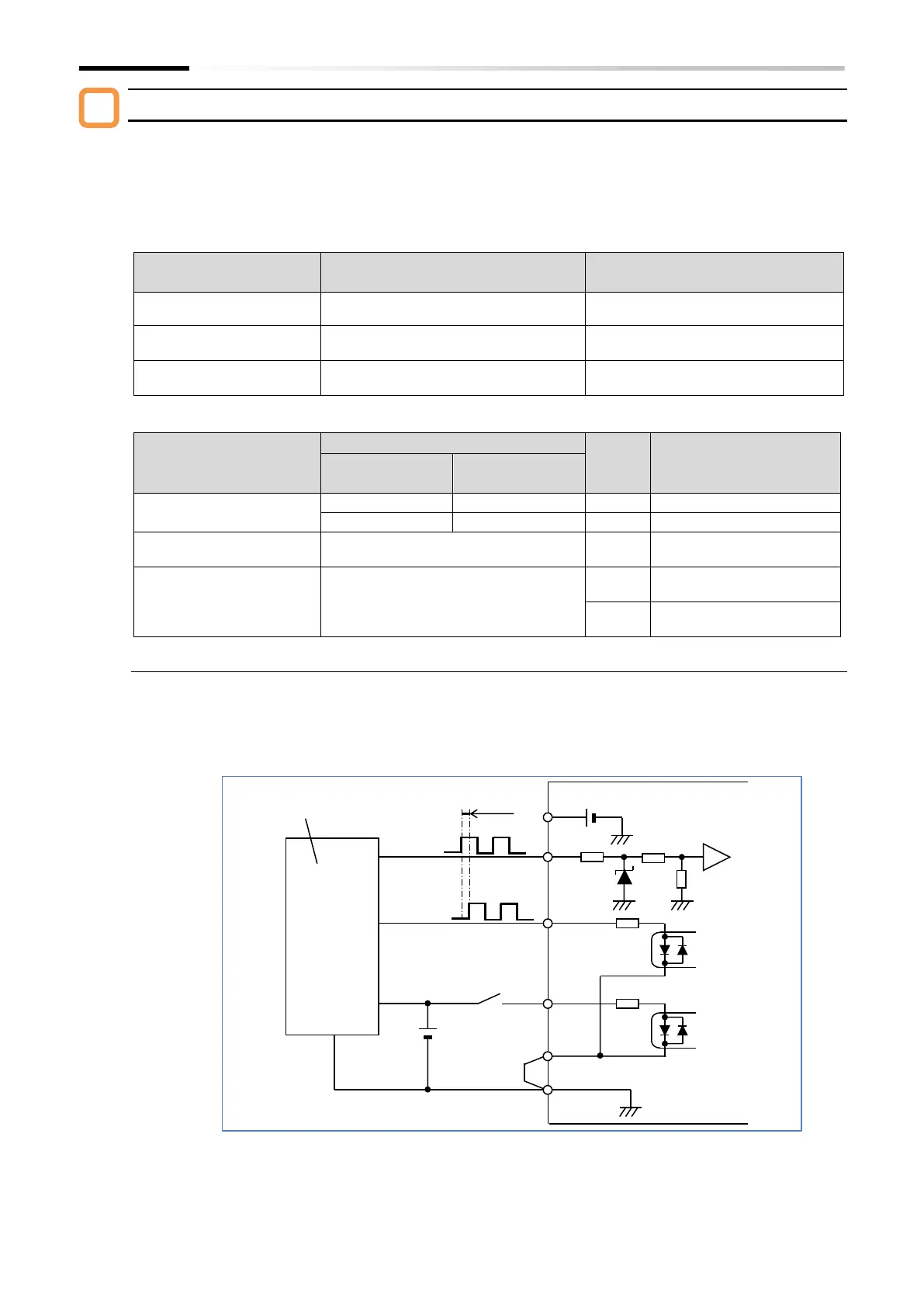
■ Phase AB 90° phase shift pulse wiring ([P004]=01)
Wire the phase AB 90° phase shift pulse input to the [PLA] and [PLB] terminals as shown in the
figure below. As the [PLB] terminal is also used with input terminal [7], use all intelligent input
terminals, including the [PLB] terminal, with source logic (voltage output-type encoder or PNP
open collector-type encoder). In addition, set the input voltage high level within intelligent input
terminal specifications (18 to 24 VDC).
Voltage output-type or PNP
open collector-type encoder
Forward rotation:
90° advance

 Loading...


