Chapter 11 RS485 Communication
11-3-2
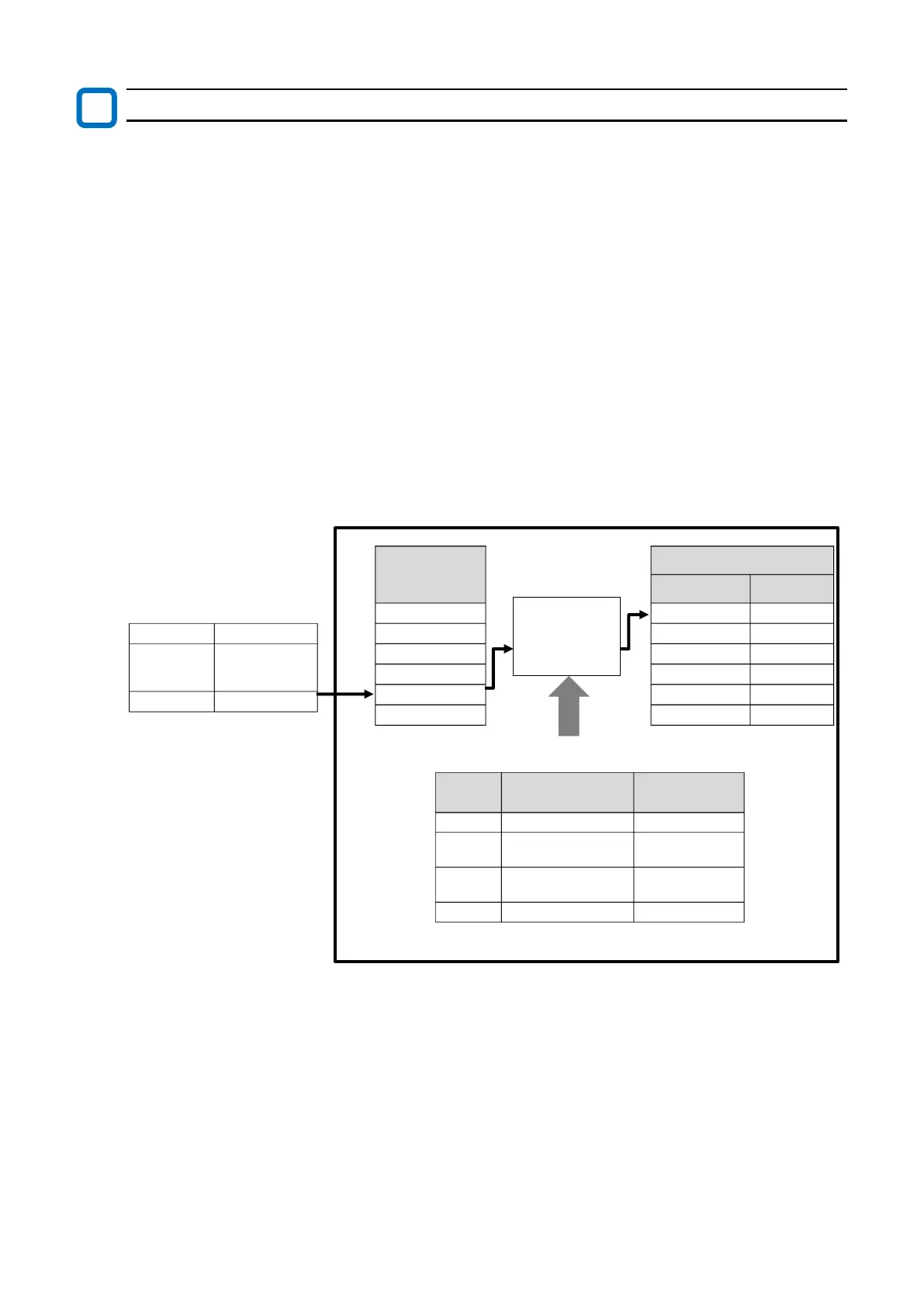
Modbus mapping configuration process
(1) Set the register number of the external control equipment to "External register 1 to 10 ([P201]
to [P210])". If "0000" is set, processing will not be performed.
(2) Set the data type of the external control equipment to "External register 1 to 10 format
([P211] to [P220])".
(3) In "External register 1 to 10 scaling ([P221] to [P230])", set the magnification when receiving
from an external control equipment and capturing it inside the inverter. Conversely, when
internal data is read, it is divided.
(4) Set Modbus register numbers inside the inverter to be actually accessed to "Internal register 1
to 10 ([P301] to [P310])".
* For Modbus register number of the inverter, refer to "18.2 List of Parameters and Modbus
Holding Registers". In addition, "2 register length parameter" cannot be set as an internal
register. In this case, access the internal register directly. Alternatively, refer to " List of 2
register length parameters accessible as 1 register length" in the table below, and use these
register numbers as internal registers.
(5) Set "Endian selection [P400]" as required. For details, refer to "11.2.11 Endian Selection of
Holding Registers".
(6) Set "Register mapping selection [P200]" to "Enable Modbus mapping function (01)". When the
parameters related to Modbus mapping function have been set or changed, be sure to turn
the inverter power OFF and then ON again. Settings or changes to Modbus mapping function
will not be reflected unless the power is turned on again.
1000d is written.
Consider the data type of the external data as unsigned and write 2000d multiplied by 2.00 of the
scale to the internal register. (In case of data reading, the internal data is returned to the external
control equipment by 1/2.)

 Loading...


