Chapter 16 Maintenance and Inspection
16-2-4
16.2.4 Checking the Inverter and Converter Section
Checking method of inverter and converter
Using the analog multimeter, it can be checked if the inverter or converter unit are defective or non-defective.
1 Preparation
(1) Disconnect all wires to the main circuit terminal block (wires to the [R/L1], [S/L2], [T/L3],
[U/T1], [V/T2], [W/T3], [P/+], [PD/+1], [N/-], and [RB] terminals).
(2) Prepare an analog multimeter. (The use range is 1 Ω resistance measurement range.)
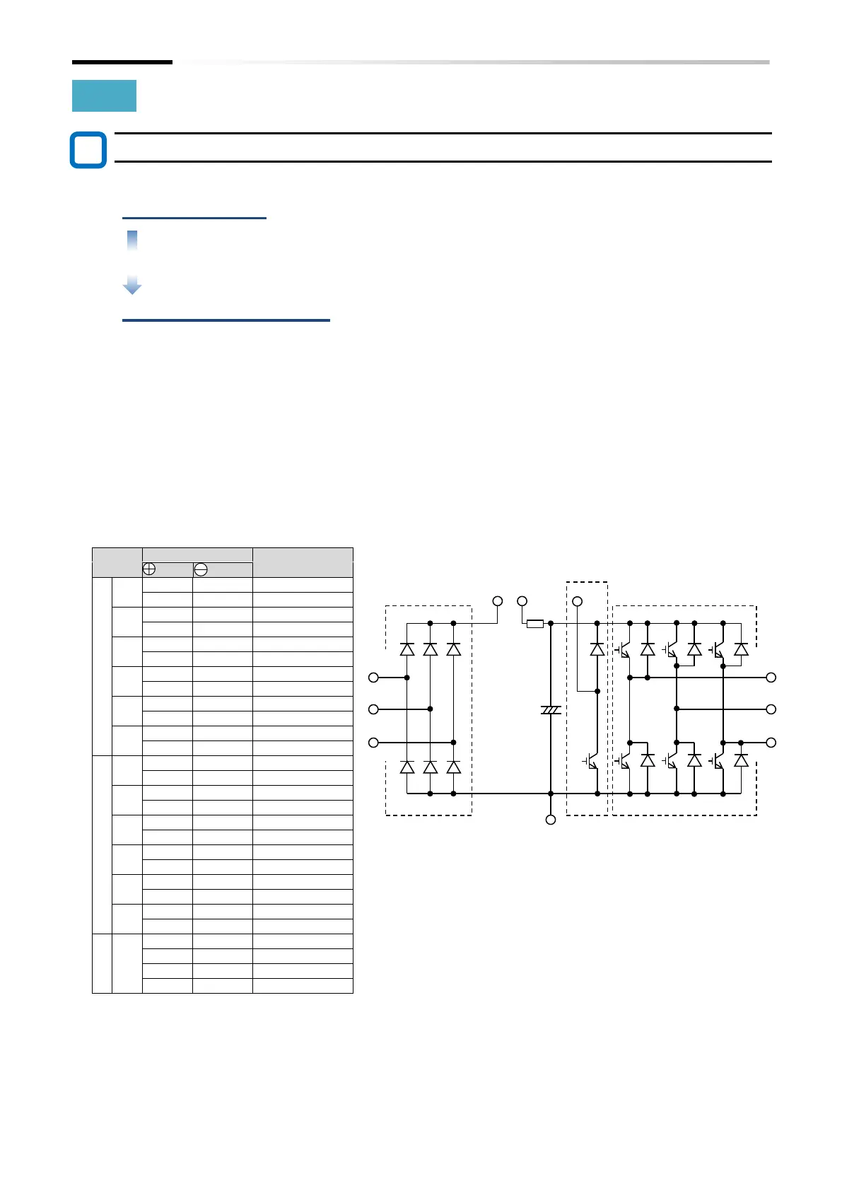
2 Checking method
The good-or-bad condition of conduction status of terminals on the inverter main circuit
terminal block [R/L1], [S/L2], [T/L3], [U/T1], [V/T2], [W/T3], [P/+], [PD/+1], [N/-] and [RB]
can be judged by alternately changing the polarity of tester for measurement.
By measuring the voltage between P and N in the DC voltage range, check that
electricity is fully discharged from the smoothing capacitor before performing check.
When electricity is not conducted, the value is almost infinite. (When conducting, it
indicates several ohms to several tens of ohms.)
Due to effects of the smoothing capacitor, electricity may be conducted instantly and
may not show infinity value. The measured values vary depending on the element type,
tester type, etc., but it is acceptable if the values in each section are nearly equal. The
measured value may be shifted by several ohms due to the current limiting resistance for
preventing inrush current.

 Loading...


