Chapter 2 Outline of This User's Guide/Procedure for Operation
2-1-3
■ What this Guide explains.
Chapter 2 Outline of This User's Guide/
Procedure for Operation (this chapter)
Provides an overview of required procedures and the
chapters to be referred before test run in flowchart
Chapter 7 Keypad and Related Functions
Explains how to operate the inverter.
Chapter 12 ProDriveNext/EzSQ
Provides an overview of what can be
done by connecting to a computer.
Chapter 17
Specifications/Dimensions/Derating
Describes the inverter specifications,
external dimensions and current derating
characteristics.
Chapter 10 Monitor Functions
Describes various data that can be
monitored by the inverter.
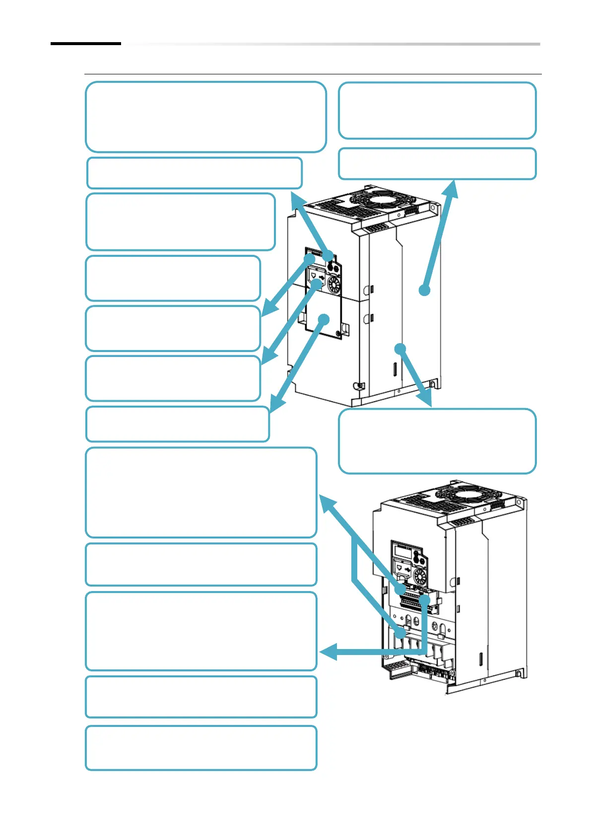
Chapter 3 Main Body of the Product
Describes the package, specification label,
appearance, and name of each part of the
product.
Chapter 4 Installation
Describes the installation of the product.
Chapter 13 Option Board
Describes the supported option boards.
Chapter 5 Wire Connection
Describes the wirings of the power line, motor line
and optional device such as reactor and braking
resistor to the main circuit terminal block.
Also describes the wiring of the I/O contacts, relay
output, analog I/O and so on to the control circuit
terminal block.
Chapter 9 Inverter Functions
Describes the functions that can be
performed with the inverter.
Chapter 8 Mandatory Setting for Motor
Describes the settings required to drive
Chapter 15 Tips/FAQ/Troubleshooting
Describes the countermeasures for trip and warning
occurrence.
Chapter 16 Maintenance and Inspection
Describes maintenance and inspection, such as
Chapter 11 Modbus Communication
Chapter 14 Safety Function STO
Describes detailed information when Modbus
communication and safety function STO are used.
For the wiring, also refer to "5.4 Control Circuit
Chapter 6 Operation Check/Residual Risk
Describes residual risks during operation and the

 Loading...


