EasyManuals Logo

Hitachi WJ C1 Series User Manual

Hitachi WJ C1 Series
494 pages
To Next Page IconTo Next Page
To Previous Page IconTo Previous Page
Page #476 background imageLoading...
Page #476 background image
Appendix
A-1-7
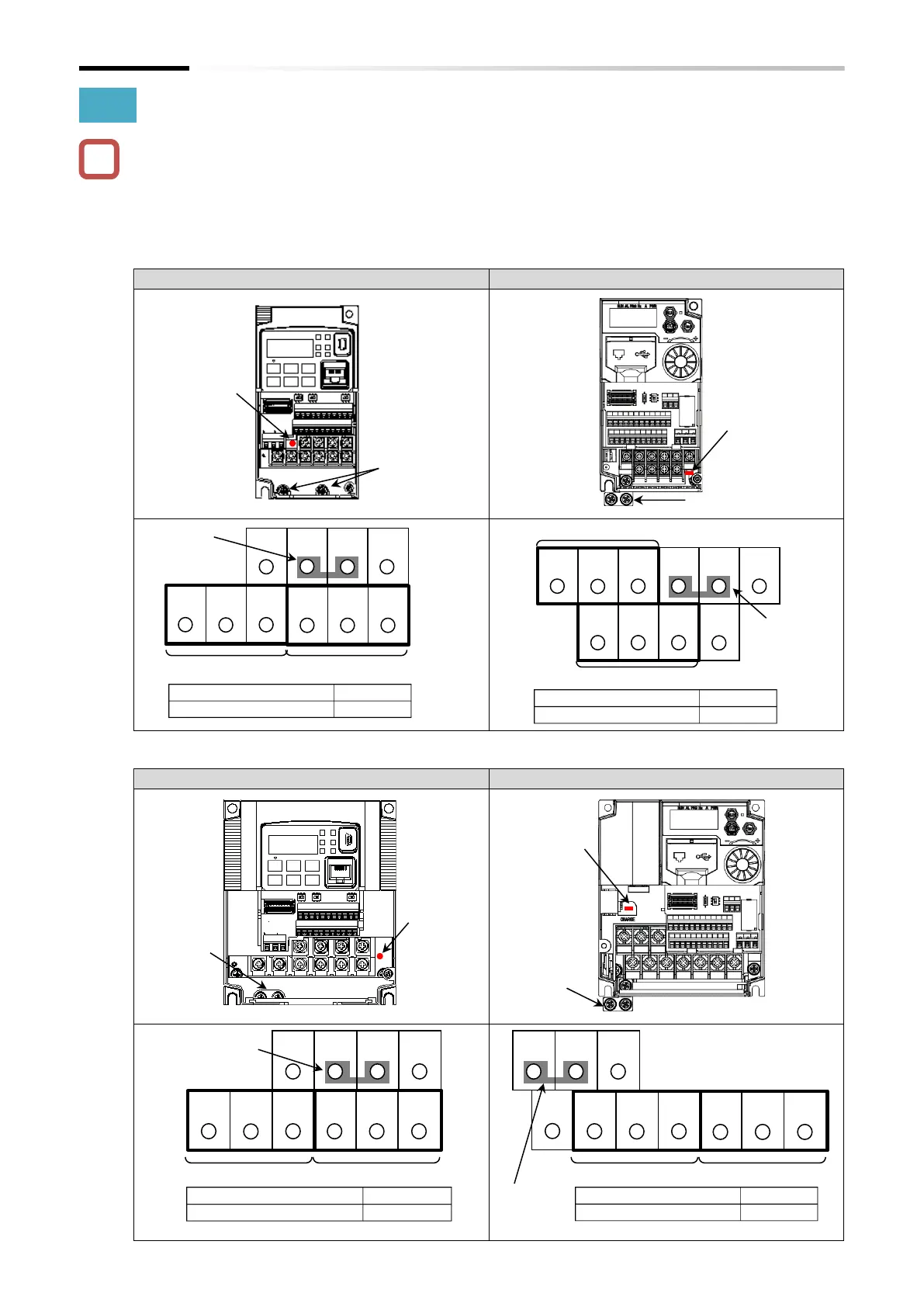
A.1.2 Comparison of Main Circuit Terminal Block
 The main circuit terminal block arrangement of WJ200 Series and WJ-C1 differs greatly. Be
careful not to make incorrect wiring during replacement, etc.
 In WJ-C1 single-phase 200 V all models/three-phase 200 V 0.1 to 3.7 kW/three-phase 400 V
0.4 to 4.0 kW, the ground terminal is the ground bar (M4×2) on the left side of the bottom of the
inverter.
â–  Single-phase 200 V 0.1 kW to 0.4 kW
WJ200-001SF/002SF/004SF
C1-001SF/002SF/004SF
â–  Single-phase 200 V 0.75 kW to 2.2 kW
WJ200-007SF/015SF/022SF
C1-007SF/015SF/022SF
Screw size
M3.5
Terminal block width
7.6 mm
Power supply input
wire
Motor output wire
W/T3
V/T2
U/T1
RB
+
+1
N
L1
-
Short-
circuit bar
Power supply input wire
Motor output wire
W/T3
V/T2
U/T1
RB
+
+1
N
L1
-
Short-
circuit
bar
Screw size
M3.5
Terminal block width
7.3 mm
Screw size
M4
Terminal block width
10 mm
Power supply input wire
Motor output wire
W/T3
V/T2
U/T1
RB
+
+1
N
L1
-
Short-
circuit bar
Screw size
M4
Terminal block width
9.9 mm
Short-
circuit bar
Power supply input
wire
Motor output wire
W/T3
V/T2
U/T1
RB
+
+1
N
L1
-
!
Charge
lamp
Ground
terminal
M4×2
Charge
lamp
Ground bar M4×2
Charge
lamp
Ground
terminal
M4×2
Charge
lamp
Ground bar
M4×2

Table of Contents

Questions and Answers:

Question and Answer IconNeed help?

Do you have a question about the Hitachi WJ C1 Series and is the answer not in the manual?

Hitachi WJ C1 Series Specifications

General IconGeneral
BrandHitachi
ModelWJ C1 Series
CategoryInverter
LanguageEnglish

Related product manuals