Drive Configuration D2 Series Servo Drive User Manual
5-18 HIWIN MIKROSYSTEM CORP.
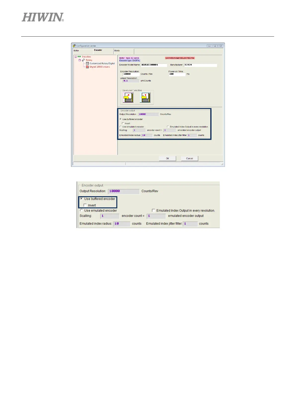
Figure5.2.2.3.1 Encoder output setting area
Figure5.2.2.3.2 Buffered encoder output
(2) Emulated encoder output
When this option is selected, the drive will multiply the received encoder position by “Scaling” and
send the result to the host controller. If the ratio is 1:1, the drive will directly output the encoder signal
based on the adopted encoder and the set resolution. At the some cases, the host controller cannot
receive the encoder signal with a high frequency. Hence, a different ratio can be used, e.g., 5
encoder counts = 1 emulated encoder output. On the other hand, if the multiplier factor of analog
encoder is set too small, “Scaling” might be needed to reduce the resolution of encoder output. The
output direction can be changed by setting 1 encoder count = -1 emulated encoder output. Taking
the emulated encoder output in figure 5.2.2.3.4 as an example, the encoder resolution is 10,000
counts/rev and the scaling for emulated encoder output is 5 encoder counts = 1 emulated encoder
output. Therefore, “Output Resolution” is zoomed in to 2,000 counts/rev.
Note:
The function of emulated encoder output will temporarily loss efficacy when parameters are saved to Flash.
 Loading...

