D2 Series Servo Drive User Manual Drive Tuning
HIWIN MIKROSYSTEM CORP. 6-29
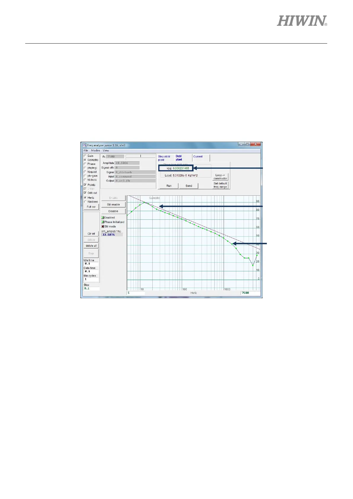
Step 4: Click the left mouse button on the frequency response diagram to appear the cursor line of
-20 dB. Press and hold the left mouse button to drag the cursor line to close to the line of
frequency response, as shown in figure 6.6.3.4. Dragging the line will re-calculate the gain
and display the vpg value at any time. The gain is increased when the cursor line is
dragged downward; while decreased when it is dragged upward.
Step 5: Click the “Send” button to send the velocity loop gain to the drive. If the setting needs to be
saved, do not forget to save it in the drive’s Flash.
Figure6.6.3.4
via the
automatic
calculation.
response
line
line

 Loading...
