Drive Tuning D2 Series Servo Drive User Manual
6-36 HIWIN MIKROSYSTEM CORP.
Before using the friction compensation function, the Lightening HMI provides a convenient set of steps.
The friction compensation can be successfully added after completing each step.
Step 1: Click the “Set scope” button to show the “Scope” window.
Step 2: Set “friction compensation” in figure 6.6.7.1 to 0.
Step 3: Set “Dwell time” to 500 ms.
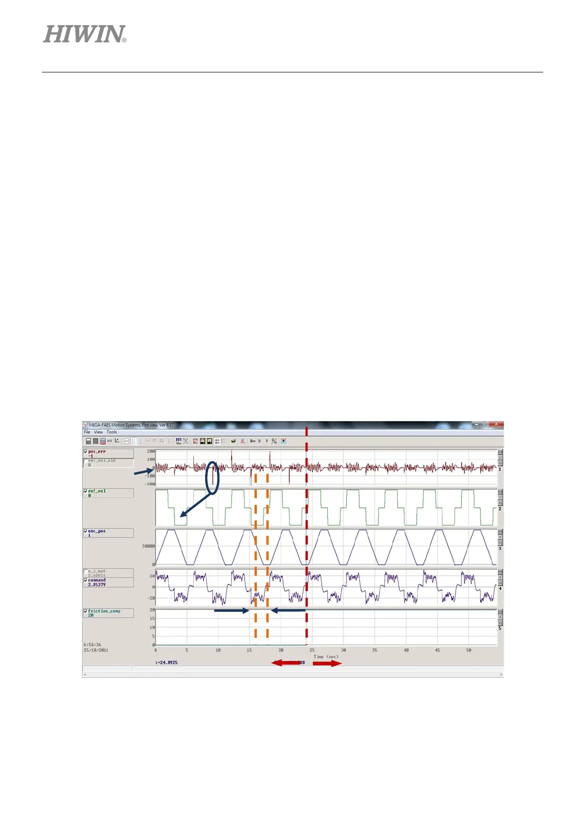
Step 4: Set the desired speed and make the motor to do the back-and-forth motion. Observing “Position
Error” in “Scope” can determine whether the friction compensation is necessary to add or not. If
the motor has a large position error at the start, as shown in the left side of figure 6.6.7.2, the
friction compensation can be added to improve the position error.
Step 5: Observe “Command Current” at the constant speed, and calculate the average value. In the
example of figure 6.6.7.2, the average value of “Command Current” is 20.
Step 6: Enter the average value obtained from Step 5 into the “friction compensation” field.
Step 7: Observe whether “Position Error” is reduced at the start of motor movement. As shown in the
right side of figure 6.6.7.2, it can be found that the friction compensation does reduce the
position error.
Figure6.6.7.2
large position
Disable the friction compensation
Enable the friction compensation
 Loading...

