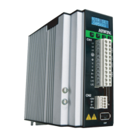
D2 Series Servo Drive User Manual LCD Operation
HIWIN MIKROSYSTEM CORP. 7-3
7.1.2 Operation page description
There are four modes on the display panel: home page, display parameters page, change parameters
page, and actions page. Press the F key to switch to other mode. The overall structure of LCD is shown in
figure 7.1.2.1.
(1) Home page
It mainly shows the servo enable state of drive, error message or warning message, and the axis
name of servo axis.
(2) Display parameters page
It mainly shows the motor feedback position, reference position, position error, feedback velocity,
reference velocity, I/O statuses, motor statuses (phase initialization, motor movement, homing, error
map), and other parameters.
(3) Change parameters page
It mainly is used to change the common gain, velocity loop gain, phase initialization gain, operation
mode, pulse format, and other parameters, and to save parameters in the memory to Flash. More
than 200 advanced parameters can be set.
(4) Actions page
It is mainly for the servo enable or disable, continuous motion (Jog), moving to the absolute target
position, setting the current position to zero, “Auto Tune”, selecting the motor model name, and other
actions.

 Loading...