LCD Operation D2 Series Servo Drive User Manual
7-40 HIWIN MIKROSYSTEM CORP.
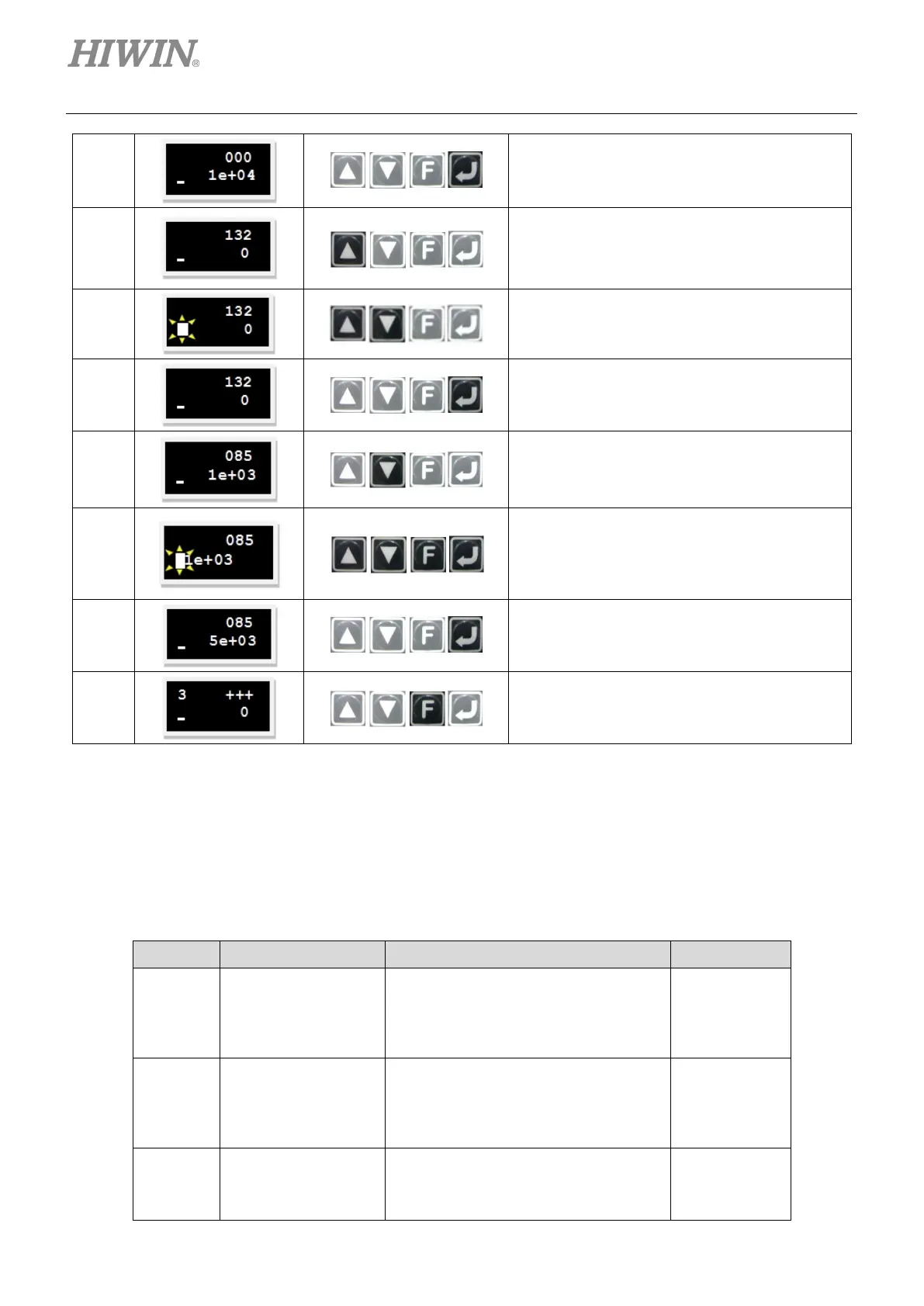
3
Press the Enter key to enter the advanced
parameter zone.
4
Press and hold the Up key to go to LCD No. 132
pag
e (refer to note 1), i.e. the setting page of
input command format for the
velocity and
torque modes.
5
Press the Up key or Down key to set this
parameter to the required value. (Note. This
example is the analog command input.)
6
Press the Enter key to complete the “input
command format” setting.
7
Press and hold the Down key to go to LCD No.
085 page (refer to note 1), i.e. the setting page
of current command scale.
8
Press the Enter key first and set this parameter
to the required value. (
To invert the voltage or
PWM command, simply add a minus sign to
“current command scale”.)
9
Press the Enter key to complete the “current
command scale” setting.
10
Press and hold the F key to go back to the “+++”
page, i.e. the common parameter zone.
To set the dead band for current command (LCD No. 086), the setting procedure is the same as that
for setting current command scale (LCD No. 085).
Note:
The input command format can be set via following parameters.
Table7.7.3.3
LCD No. Parameter Definition Initial value
132
X_cmd_pwm_mode
Input command format for the velocity
and torque modes
0: Analog
1: PWM 50%
0
085
X_cmd_ext_i_sc
Current command scale; the output
current corresponds to 1 V, or the
maximum current corresponds to Full
PWM. (unit: A
amp
= 1 V or A
amp
= Full
Motor peak
current/10
086
X_cmd_ext_i_dz
Dead band of current command. The
current command is 0 when the input
voltage is less than the set value.
0
 Loading...

