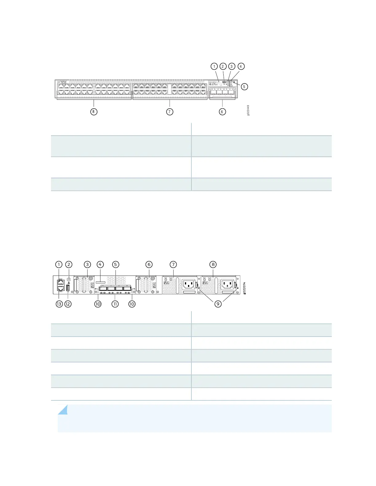
Figure 41: Components on the Front Panel of EX4300-48MP and EX4300-48MP-S Switches
5—1— Factory Reset/Mode buttonQR code
6—2— 4-port 1-Gigabit Ethernet SFP/10-Gigabit Ethernet
SFP+ uplink module (optional)
Mini-USB console port
7—3— 100/1000/2500/5000/10000 Ethernet Network
Ports
Chassis status LEDs
8—4— 10/100/1000BASE-T Ethernet Network PortsPort status mode LEDs
Figure 42 on page 83 shows the components on the rear panel of a 24-port and 48-port EX4300 switch
except EX4300-48MP and EX4300-48MP-S switches (with two AC power supplies and two fan modules
installed).
Figure 42: Components on the Rear Panel of a 24-Port and 48-Port EX4300 Switch Except EX4300-48MP
and EX4300-48MP-S Switches
8—1— AC power supply in slot 1Management port
9—2— Power supply slot numbersESD point
10—3— Fan module slot numbers and LEDsFan module in slot 0
11—4— QSFP+ port LEDsSerial number label
12—5— USB portQSFP+ ports
13—6— Console portFan module in slot 1
7—AC power supply in slot 0
NOTE: DC power supplies are installed in the power supply slots in models that use DC power.
83

 Loading...


