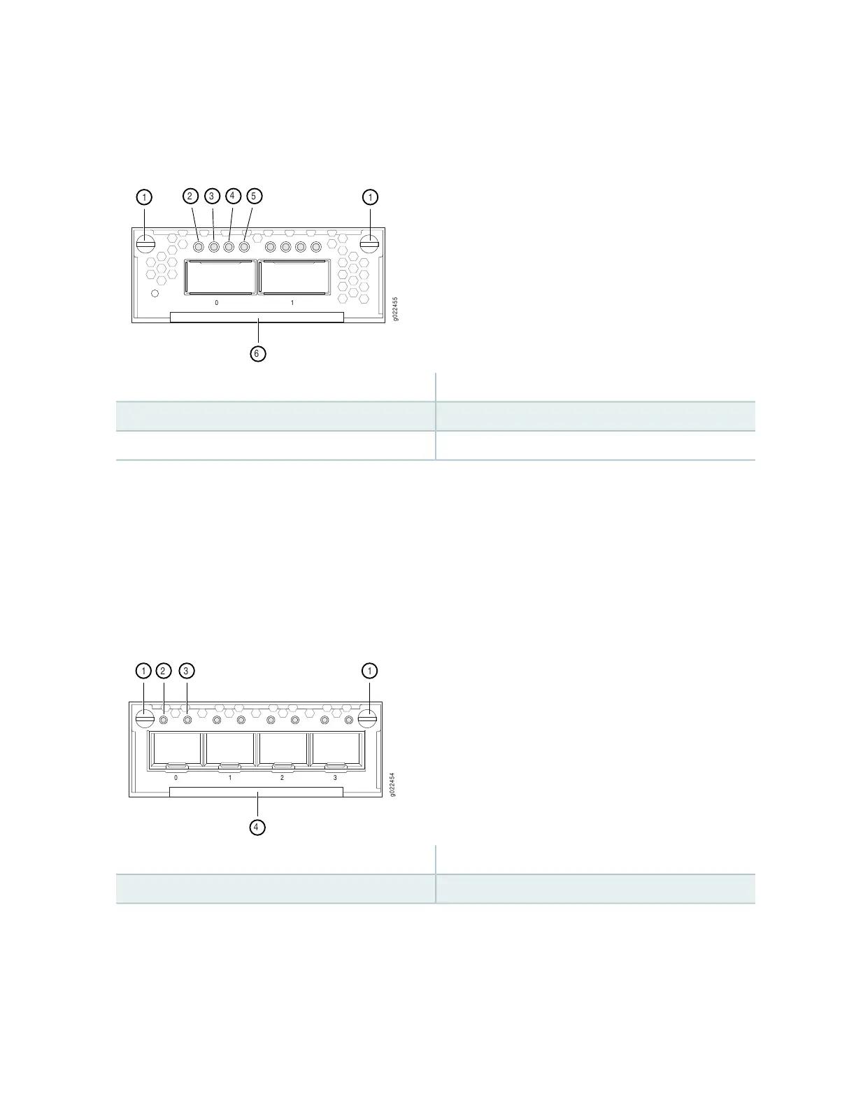
Figure 212: LEDs on the Ports on the 2-Port 40-Gigabit Ethernet QSFP+/100-Gigabit Ethernet QSFP28
Uplink Module for EX4300-48MP and EX4300-48MP-S Switches
4—1— Link activity LED of the uplink module portCaptive screws of the uplink module
5—2— Link activity LED of the uplink module portLink activity LED of the uplink module port
6—3— Handle of the uplink moduleLink activity LED of the uplink module port
There are four LEDs for each port (labeled 2, 3, 4, and 5 in Figure 212 on page 569). If a port is configured
to operate at 10-Gbps speed by using breakout cables, four 10-Gbps interfaces are created and the four
LEDs for that port becomes operational. Each of these LEDs indicates the link activity on the corresponding
interface. If a port is configured to operate at 40-Gbps or 100-Gbps speed, the LED labeled 2 for that port
in Figure 212 on page 569 becomes operational and indicates the link activity on the corresponding port.
Figure 213: LEDs on the Ports on the 4-Port 1-Gigabit Ethernet SFP/10-Gigabit Ethernet SFP+ Uplink
Module for EX4300-48MP and EX4300-48MP-S Switches
3—1— Status LED of the uplink module portCaptive screws of the uplink module
4—2— Handle of the uplink moduleLink activity LED of the uplink module port
The Table 121 on page 570 describes the link activity LED on 10/100/1000BASE-T network ports, SFP
network ports, SFP+ uplink ports, SFP+ uplink module ports, built-in QSFP+ ports, QSFP+ uplink module
ports, and QSFP+/QSFP28 uplink module ports.
569

 Loading...


