215575 106 Revision B
$
%
&
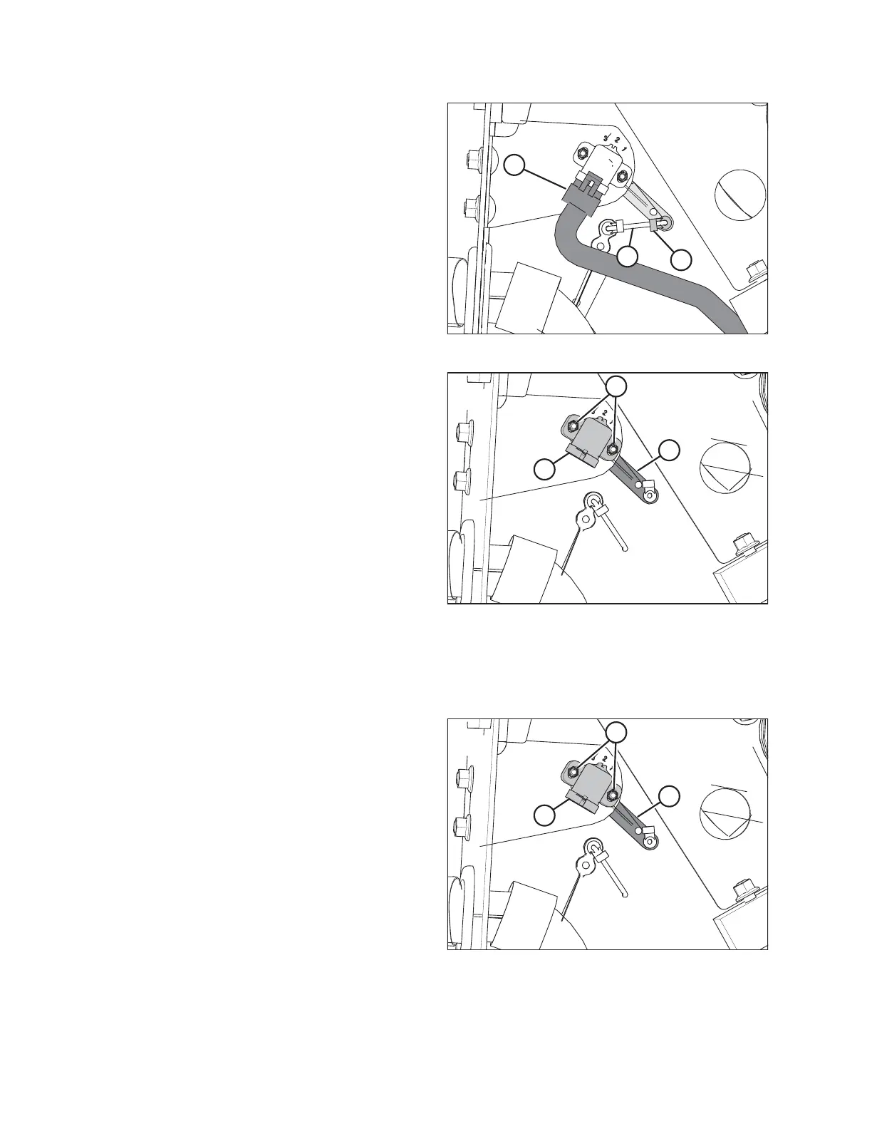
Figure 4.3: Header Height Sensor Assembly – Left Side
4. Disconnect wire harness (A).
5. Push up on rod end clip (B). Slide linkage rod (C) out of rod
end clip (B).
%
&
$
Figure 4.4: Header Height Sensor Assembly – Left Side
6. Remove nuts and bolts (A).
7. Remove sensor (B) and control arm (C).
NOTE:
Note the orientation of the control arm before removing it.
The new control arm must be reinstalled in the same
orientation.
4.3.2 Installing Header Height Sensor Assembly — Left Side
Be sure to install the left header height sensor with its control arm in a position identical to that of the removed sensor.
%
&
$
Figure 4.5: Header Height Sensor Assembly – Left Side
1. Install control arm (C). Ensure that the flat side is facing
towards the header.
2. Install sensor (B). Install the bolts in their slots and secure
them with nuts (A).
AUTO HEADER HEIGHT CONTROL