215575 146 Revision B
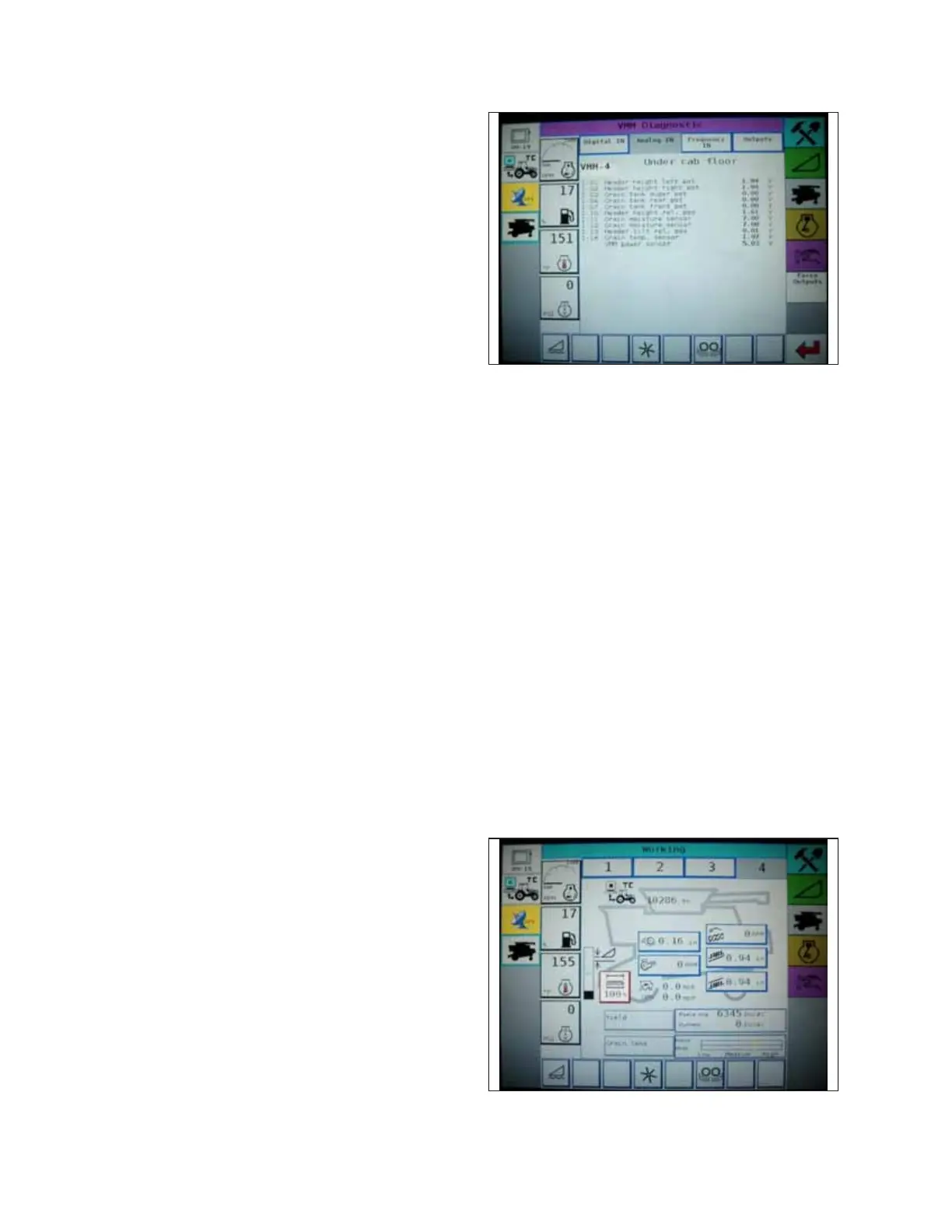
Figure 4.90: Challenger
®®
Combine Display
5. Fully lower the combine feeder house.
NOTE:
You may need to hold the HEADER DOWN switch for a few
seconds to ensure that the feeder house is fully lowered.
6. Record the height sensor voltage.
7. Raise the header so that the cutterbar is 150 mm (6 in.) off
of the ground.
8. Record the height sensor voltage.
9. If the sensor voltage is not within the low and high limits shown in 4.4 Height Sensor Output Voltage Range – Combine
Requirements, page 111 , or if the range between the low and high limits is insufficient, the voltage range of the height
sensors may require adjustment. For instructions, refer to 4.8.4 Adjusting Header Height – Challenger
®
6 Series, page
149.
4.8.2 Engaging Auto Header Height Control – Challenger
®®
6 Series
Set these initial configuration options on your Challenger
®
6 Series combine when setting up the auto header height
control (AHHC) system.
NOTE:
Changes may have been made to the combine controls or the display since this document was published. Refer to the
combine operator’s manual for updated information
The following system components are required for the auto header height control (AHHC) to work:
• The main module (PCB board) and header driver module (PCB board) mounted in the card box in the fuse panel
module (FP)
• The multifunction control handle operator inputs
• The operator inputs mounted in the control console module (CC) panel
NOTE:
The electro-hydraulic header lift control valve is also an integral part of the system.
Figure 4.91: Challenger
®®
Combine Display
1. Using the header control switch, scroll through the header
control options on the combine display until the AHHC icon
is displayed in the first message box. The AHHC will adjust
the header height in relation to the ground according to the
height setting and the sensitivity setting.
AUTO HEADER HEIGHT CONTROL