215575 127 Revision B
Figure 4.48: Header Control Cluster
4. Use HEADER HEIGHT SETPOINT control dial (A) as necessary
to fine-tune the header position.
4.5.5 Reviewing Header In-Field Settings – IDEAL
™™
Series
Once the auto header height control (AHHC) system is working correctly with your IDEAL
™
combine, you can fine-tune
these AHHC settings to your liking.
NOTE:
Changes may have been made to the combine controls or the display since this document was published. For instructions,
refer to the combine operator’s manual for updated information.
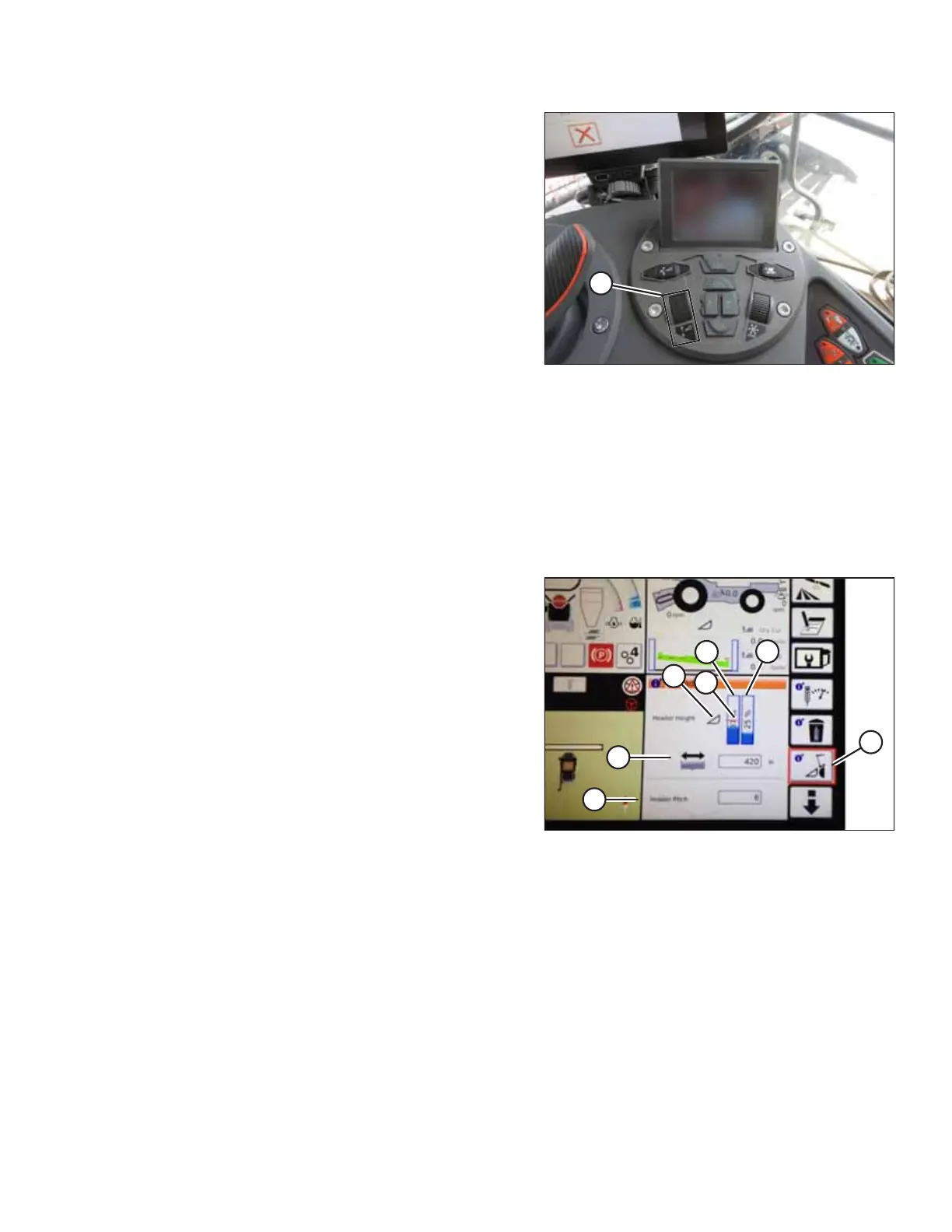
Figure 4.49: Header Groups
1. To view the header group settings, touch HEADER icon (A)
on the right side of the home page.
2. The following information is displayed:
• CURRENT POSITION of header (B).
• SETPOINT cut-off position (C) (indicated by the red line)
• HEADER symbol (D) – touch this to adjust the setpoint
cut-off position using the adjustment wheel on the right
side of the Tyton terminal.
• CUT HEIGHT for AHHC (E) – fine-tune this setting with
the header height setpoint control dial on the header
control cluster.
• HEADER WORKING WIDTH (F)
• HEADER PITCH (G)
AUTO HEADER HEIGHT CONTROL