215575 139 Revision B
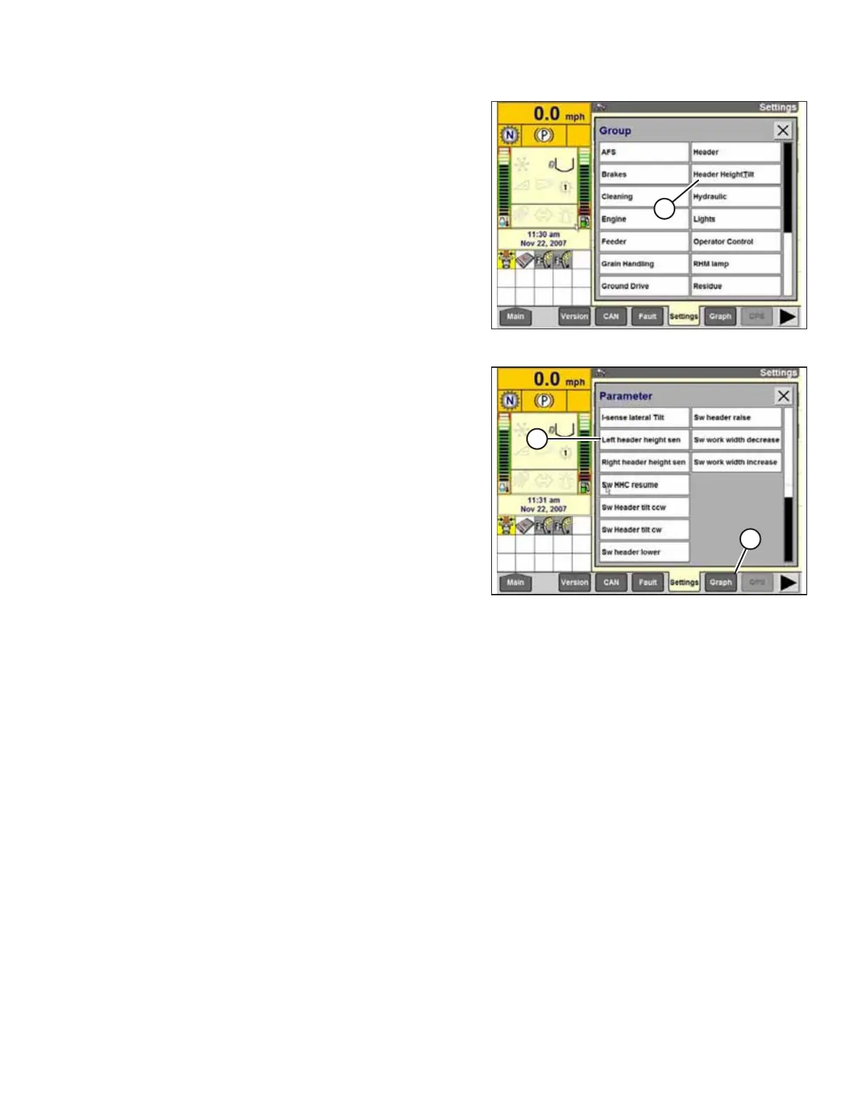
Figure 4.74: Case IH Combine Display
5. Select HEADER HEIGHT/TILT (A). The PARAMETER
page appears.
Figure 4.75: Case IH Combine Display
6. Select LEFT HEADER HEIGHT SEN (A) and then select GRAPH
button (B). The exact voltage is displayed at the top of the
page. Raise and lower the header to see the full range of
voltage readings.
7. If the sensor voltage is not within the low and high limits
shown in 4.4 Height Sensor Output Voltage Range –
Combine Requirements, page 111, or if the range between
the low and high limits is insufficient, the height sensors
must be adjusted. For instructions, refer to 4.4.2 Adjusting
Header Height Sensor Voltage Range – Left Side, page 114
and 4.4.3 Adjusting Header Height Sensor Voltage Range –
Right Side, page 114.
4.7.3 Calibrating Auto Header Height Control (Case IH 7010/8010; 7120/8120/9120;
7230/8230/9230; 7240/8240/9240) – Software Versions Below 28.00
The auto header height control (AHHC) sensor output must be calibrated for Case IH 7, 8, or 9 series combines with
software versions below 28.00, or the AHHC feature will not work properly.
NOTE:
This procedure applies to combines with a software version below 28.00. For instructions on calibrating the AHHC for
combines with software version 28.00 or above, refer to 4.7.4 Calibrating Auto Header Height Control (Case IH 7010/8010;
7120/8120/9120; 7230/8230/9230; 7240/8240/9240) – Software Versions Above 28.00, page 141.
NOTE:
Changes may have been made to the combine controls or the display since this document was published. For instructions,
refer to the combine operator’s manual for updated information.
1. Ensure that all header electrical and hydraulic connections are complete.
2. Select TOOLBOX on the MAIN page, and then select HEADER.
AUTO HEADER HEIGHT CONTROL