215575 300 Revision B
$
%
&
'
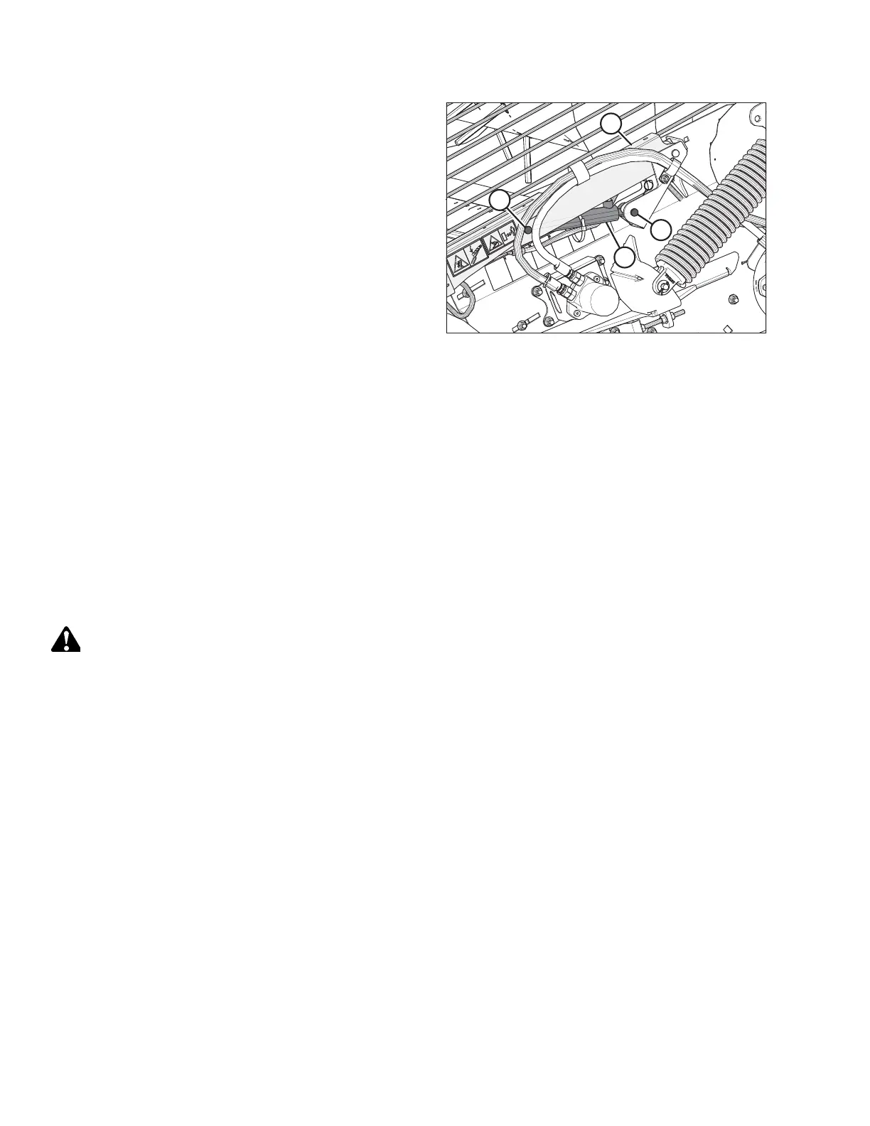
Figure 5.185: Master Cylinder — Left Side of Header
7. Position the rod end of master cylinder (A) and the safety
prop into the master cylinder support bracket.
8. Secure the rod-end of the master cylinder with shorter
clevis pin (B). Ensure that the clevis pin head faces
outboard.
9. Secure clevis pin (B) with a washer and cotter pin (not
shown).
10. Lift hold-down arm (C) until clevis pin (D) can be installed
through the lift arm and the barrel end of the master
cylinder. Ensure that the clevis pin head faces outboard.
11. Secure clevis pin (D) with a washer and cotter pin (not
shown).
12. Secure the hydraulic hoses with cable ties (not shown).
13. Remove the previously inserted block of wood.
14. Bleed the hydraulic cylinders and lines. For instructions, refer to 5.9.4 Bleeding Cylinders and Lines, page 303.
15. Close the left endshield. For instructions, refer to 3.3.2 Closing Left Endshield, page 26.
5.9.3 Replacing Slave Hold-Down Cylinder
The hold-down is raised and lowered by master and slave single-acting hydraulic cylinders. The slave cylinder is located at
the right end of the hold-down and is connected to the master cylinder by a hose that passes through the hold-down
beam.
Removing Slave Cylinder
Remove all pressure from the hydraulic system before attempting to disconnect the slave cylinder hydraulic connections.
WARNING
To avoid bodily injury or death from unexpected startup of machine, always stop the engine and remove the key from
the ignition before leaving the operator’s seat for any reason.
1. Lower the header.
2. Lower the hold-down completely.
3. Continue pressing the hold-down lower switch for 5–10 seconds to remove any pressure in the system.
MAINTENANCE AND SERVICING