215575 240 Revision B
$
%
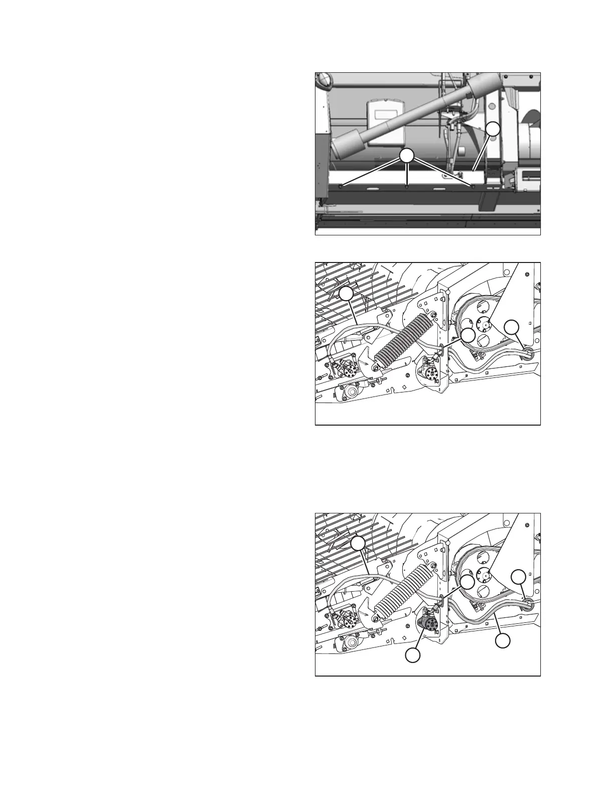
Figure 5.42: Bottom Beam Cover
9. Loosen three M12 hex flange nuts (A) and remove bottom
beam cover (B).
10. Pull the hoses out of bottom beam cover (B).
$
%
&
Figure 5.43: Left Side of Header
11. Pull hose (A) through hole (B) in the endsheet and through
hole (C) in the frame.
Installing Hydraulic Motor Hoses
The hydraulic hoses vary in length. Be sure to connect the correct hose to the correct port. Take note of the colored cable
ties to match the hoses to their respective ports.
$
'
&
%
(
Figure 5.44: Left Side of Header
1. Route two longer hoses (A) and (B) through hole (C) in the
endsheet and hole (D) in the header frame.
NOTE:
The angled fitting on hose (B) attaches to pick-up rear drive
motor (E). Hose (A) (marked with yellow cable ties) has
identical fittings at both ends and attaches to the forward
drive motor fitting equipped with a matching yellow
cable tie.
MAINTENANCE AND SERVICING