215575 114 Revision B
4.4.2 Adjusting Header Height Sensor Voltage Range – Left Side
If the voltage output range of the left header height sensor does not match the specifications, the sensor’s voltage range
must be adjusted.
DANGER
To avoid injury or death from unexpected start-up of the machine, always stop the engine and remove the key from
the ignition before leaving the operator’s seat for any reason.
1. Lower the header to the ground, shut down the combine, and remove the key from the ignition.
2. Open the left endshield. For instructions, refer to 3.3.1 Opening Left Endshield, page 25.
$
%
&
'
(
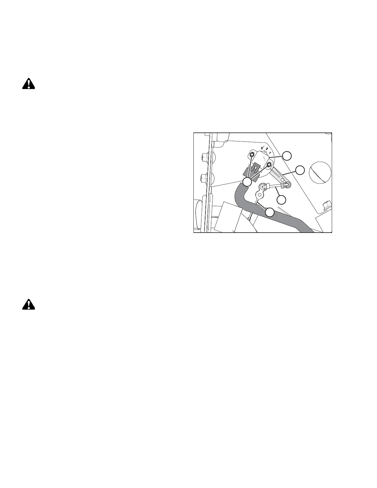
Figure 4.21: Header Height Sensor Assembly –
Left Side
3. Loosen nuts (A).
4. Rotate control (B) until the desired voltage range is
achieved. For instructions, refer to 4.4 Height Sensor
Output Voltage Range – Combine Requirements, page 111.
NOTE:
If the voltage range is too large or too small, you may need
to relocate linkage rod (C) to a different hole in sensor
control arm (D). If that doesn’t work, relocate linkage
rod (C) to a different hole in sensor control arm (E).
5. Tighten nuts (A).
6. Close the left endshield. For instructions, refer to 3.3.2
Closing Left Endshield, page 26.
4.4.3 Adjusting Header Height Sensor Voltage Range – Right Side
If the voltage output range of the right header height sensor does not match the specifications, the sensor’s voltage range
must be adjusted.
DANGER
To avoid injury or death from unexpected start-up of the machine, always stop the engine and remove the key from
the ignition before leaving the operator’s seat for any reason.
1. Raise the hold-down and engage the lift cylinder safety props.
2. Lower the header fully.
3. Shut down the engine, and remove the key from the ignition.
AUTO HEADER HEIGHT CONTROL