215575 113 Revision B
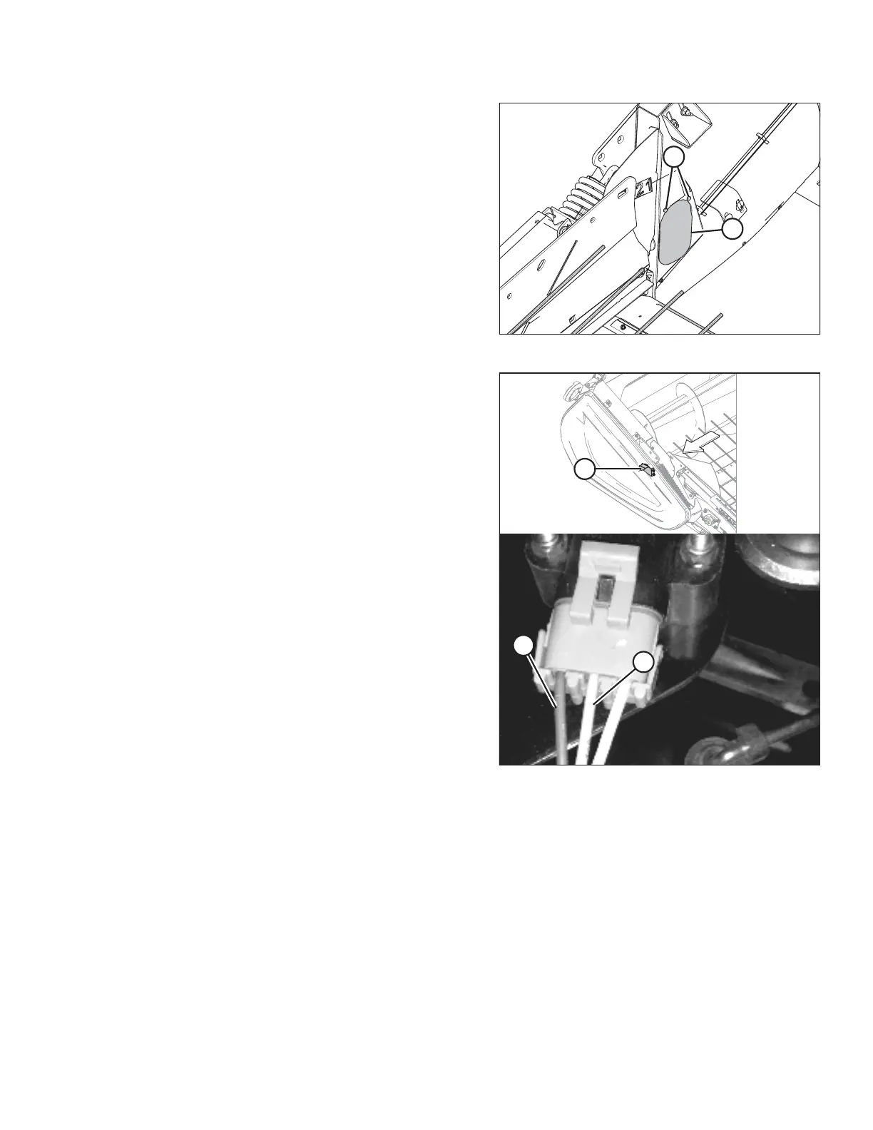
Figure 4.19: Access Panel – Right Side
7. Remove two bolts (A) and access panel (B).
NOTE:
The auger has been removed from the illustration for the
sake of clarity.
Figure 4.20: Right Height Sensor
8. Locate right height sensor (A).
NOTE:
The sensor may not be exactly as shown.
9. With the connector plugged into the sensor, measure the
voltage between orange signal wire (B) in the middle
position on the connector and brown ground wire (C) on
one side of the connector. The voltage obtained from this
reading tells you the maximum voltage for the right sensor.
10. Start the combine and fully lower the combine feeder
house. Ensure that the float springs are fully compressed.
11. Shut down the combine and position the key so that power
is still supplied to the sensors.
12. Repeat the voltage measurement procedures described in
Steps 5, page 112 and 9, page 113 for both sensors. The
voltages obtained from these readings tells you the
minimum voltages for each sensor.
13. Compare the voltage measurements to the values specified in 4.4 Height Sensor Output Voltage Range – Combine
Requirements, page 111 .
14. If the sensor voltage is outside of the low or high limits, or if the voltage range is less than the specified value,
adjustments are required. For instructions, refer to 4.4.2 Adjusting Header Height Sensor Voltage Range – Left Side,
page 114 or 4.4.3 Adjusting Header Height Sensor Voltage Range – Right Side, page 114.
AUTO HEADER HEIGHT CONTROL