215575 107 Revision B
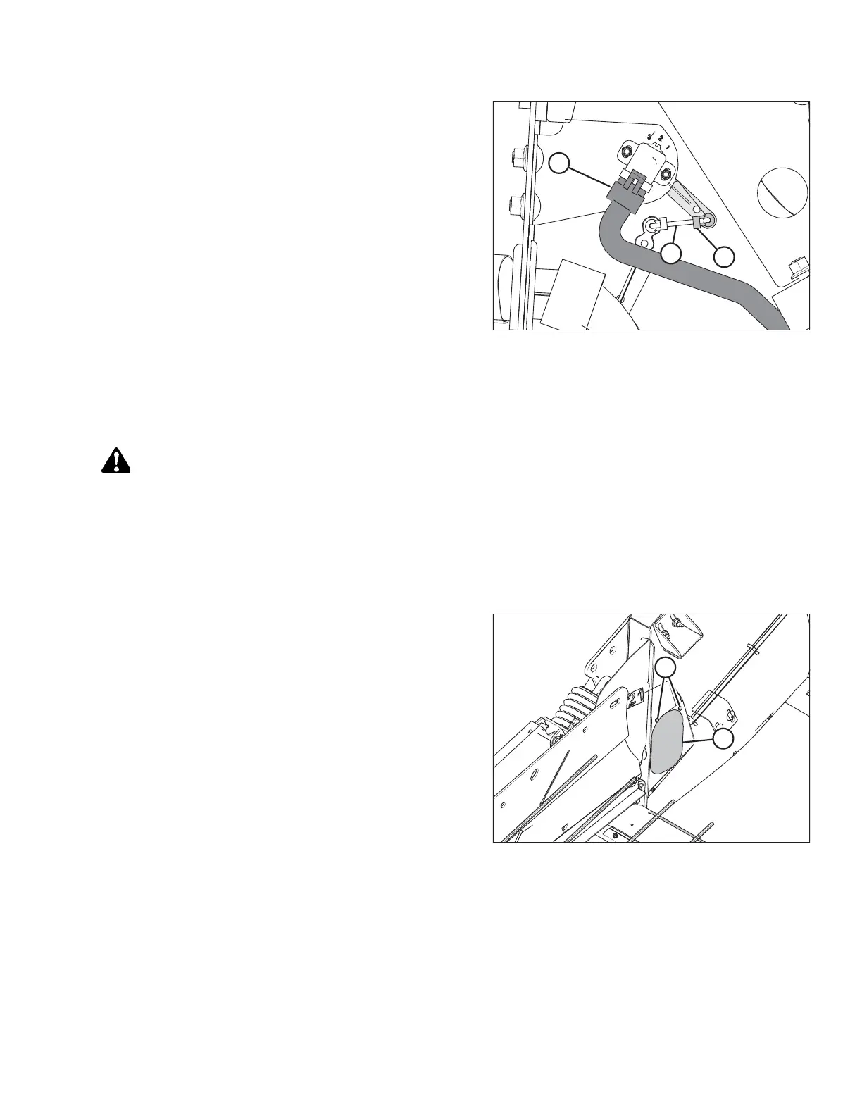
Figure 4.6: Header Height Sensor Assembly – Left Side
3. Slide linkage rod (C) into rod end clip (B). Secure the rod
end clip by pressing it onto linkage rod (C).
4. Connect wire harness (A).
5. Close the left endshield. Refer to 3.3.2 Closing Left
Endshield, page 26 for instructions.
4.3.3 Removing Header Height Control System — Right Side
Remove and replace the right header height sensor if calibration fails to resolve sensor output problems.
DANGER
To avoid bodily injury or death from the unexpected start-up or fall of a raised machine, always stop engine and
remove key before leaving the operator’s seat, and always engage safety props before going under the machine for any
reason.
1. Raise the hold-down and engage the lift cylinder safety props.
2. Lower the header fully.
3. Shut down the engine, and remove the key from the ignition.
Figure 4.7: Header Height System Access Panel –
Right Side
4. Locate the access panel on the inside of the right end
frame. Remove two bolts (A) from access panel (B).
5. Remove access panel (B).
AUTO HEADER HEIGHT CONTROL