215575 108 Revision B
$
%
&
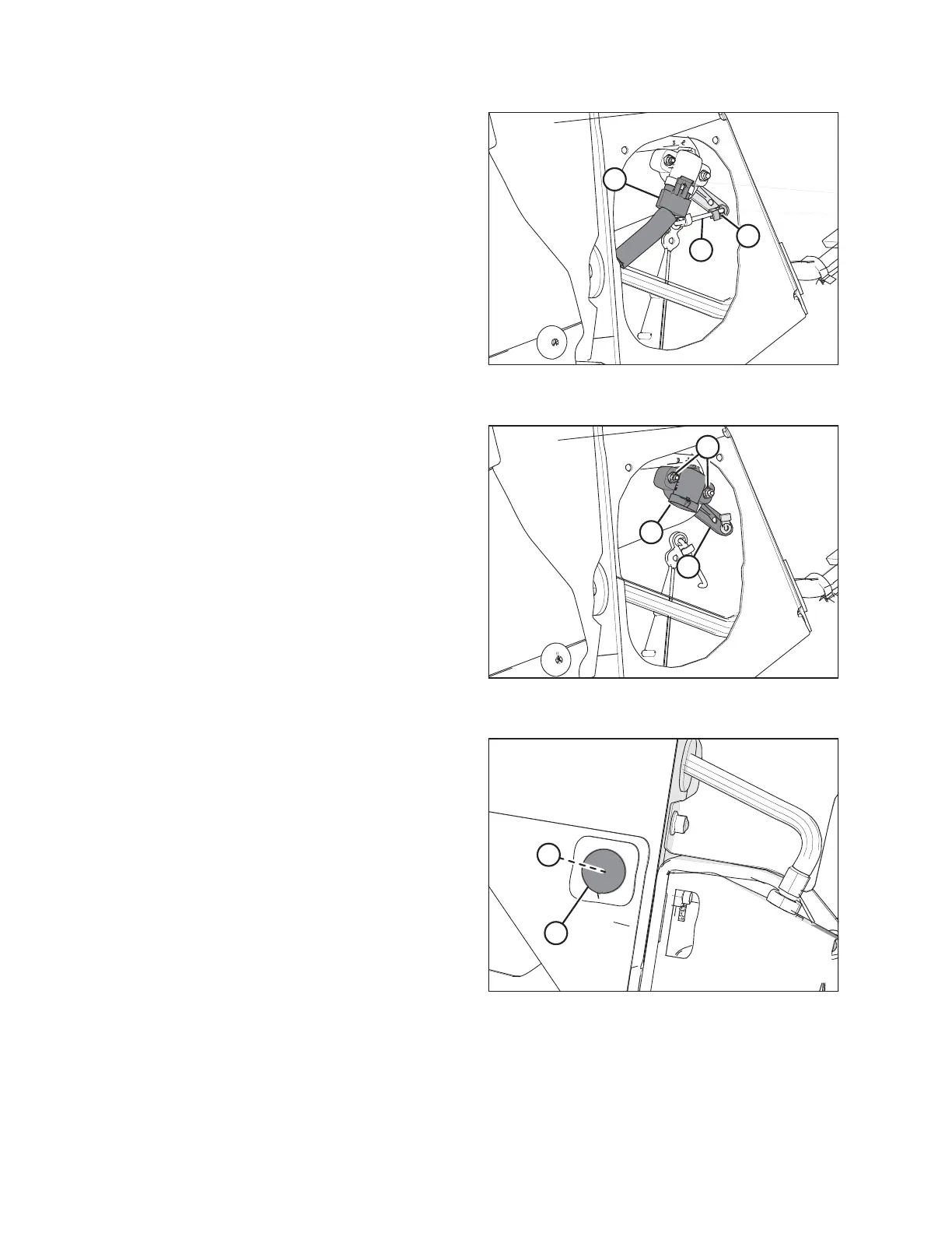
Figure 4.8: Header Height Sensor Assembly –
Right Side
6. Disconnect wire harness (A).
7. Push up on rod end clip (B). Slide linkage rod (C) out of rod
end clip (B).
%
&
$
Figure 4.9: Header Height Sensor Assembly –
Right Side
8. Remove nuts and bolts (A).
9. Remove sensor (B) and control arm (C).
NOTE:
Note the orientation of the control arm before removing it.
The new control arm must be reinstalled in the same
orientation.
$
%
Figure 4.10: Right Endsheet
10. Locate plug (A) on the outboard side of the endsheet and
remove the plug to gain access to nut (B), which secures
the long control arm to the frame.
11. Remove nut (B).
AUTO HEADER HEIGHT CONTROL