215575 115 Revision B
Figure 4.22: Access Panel – Right Side
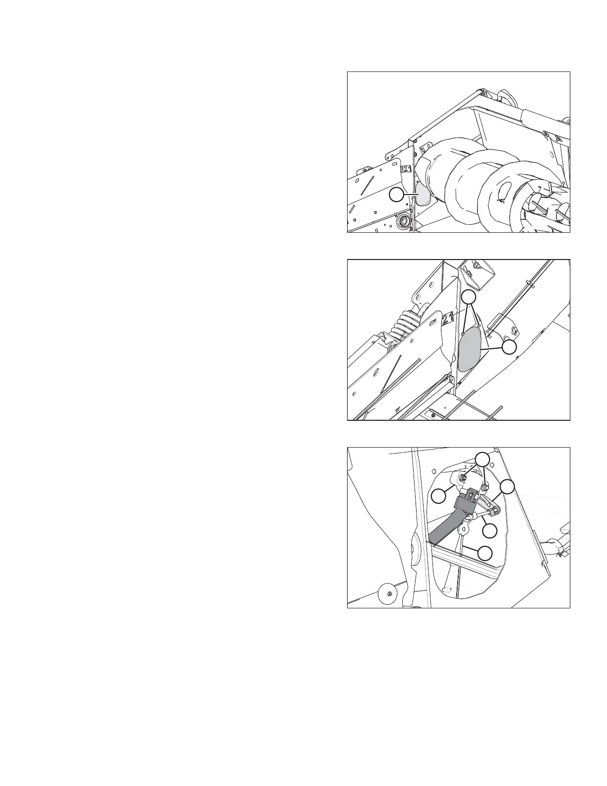
4. Locate access panel (A) on the inside of the right endsheet.
Figure 4.23: Access Panel – Right Side
5. Remove two bolts (A) and access panel (B).
NOTE:
The auger has been removed from the illustration for the
sake of clarity.
Figure 4.24: Header Height Sensor Assembly –
Right Side
6. Loosen nuts (A).
NOTE:
The auger has been removed from the illustration for the
sake of clarity.
7. Rotate sensor (B) until the desired voltage range is
achieved. For instructions, refer to 4.4 Height Sensor
Output Voltage Range – Combine Requirements, page 111.
NOTE:
If the voltage range is too large or too small, you may need
to relocate linkage rod (C) to a different hole in sensor
control arm (D). If that doesn’t work, relocate linkage
rod (C) to a different hole in sensor control arm (E).
8. Tighten nuts (A).
AUTO HEADER HEIGHT CONTROL