215575 153 Revision B
5. If the sensor voltage is not within the low and high limits shown in 4.4 Height Sensor Output Voltage Range – Combine
Requirements, page 111 , or if the range between the low and high limits is insufficient, adjustments to the height
sensors may be required. For instructions, refer to 4.4.2 Adjusting Header Height Sensor Voltage Range – Left Side,
page 114 or 4.4.3 Adjusting Header Height Sensor Voltage Range – Right Side, page 114.
4.9.2 Engaging Auto Header Height Control – Gleaner
®®
R65/R66/R75/R76 and
S Series
Set these initial configuration options on your Gleaner
®
R65/R66/R75/R76 or non-S9 S Series combine when setting up the
auto header height control (AHHC) system.
NOTE:
Refer to 4.10 Gleaner
®
S9 Series Combines, page 161 for information specific to Gleaner
®
S9 Series combines.
NOTE:
Changes may have been made to the combine controls or the display since this document was published. For instructions,
refer to the combine operator’s manual for updated information.
1. The following system components are required for the auto header height control (AHHC) to work:
• The main module (PCB board) and header driver module (PCB board) mounted in the card box in the fuse panel
module (FP)
• The multifunction control handle operator inputs
• The operator inputs mounted in the control console module (CC) panel
NOTE:
The electro-hydraulic header lift control valve is also an integral part of the system.
$
%
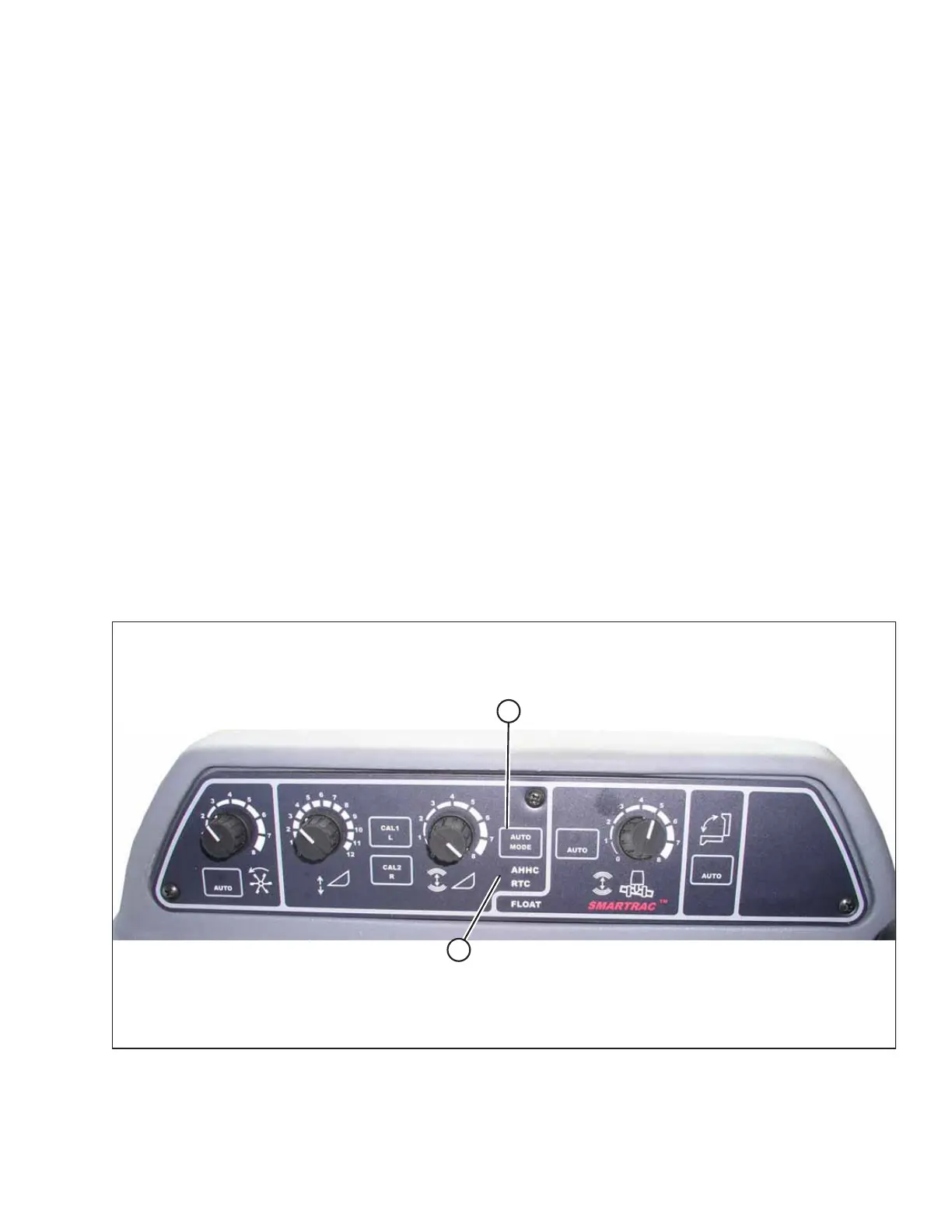
Figure 4.105: Combine Auto Header Height Controls
2. Press AUTO MODE button (A) until AHHC LED light (B) begins flashing. If the RTC light is flashing, press AUTO MODE
button (A) again until the AHHC system is activated.
AUTO HEADER HEIGHT CONTROL