215575 315 Revision B
Figure 5.217: Wheel Spindle – Left Side of Header
5. If required, remove spacer (A) from the spindle.
5.11.2 Installing Wheel
Be sure to correctly torque the wheel nut after installation.
NOTE:
The procedure below applies to the left side of the header. The right side is similar.
Figure 5.218: Wheel Spindle – Left Side of Header
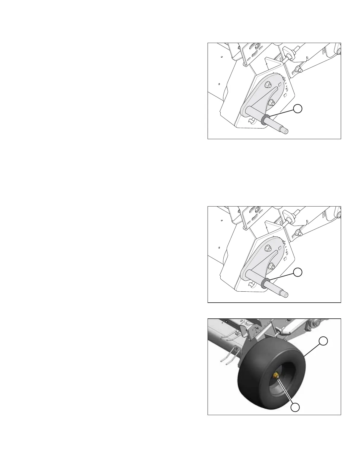
1. Ensure that spacer (A) is installed on the spindle.
Figure 5.219: Wheel – Left Side of Header
2. Install wheel (A) onto spindle and secure it with wheel
nut (B). Torque the nut to 136 Nm (100 lbf·ft).
MAINTENANCE AND SERVICING