215575 227 Revision B
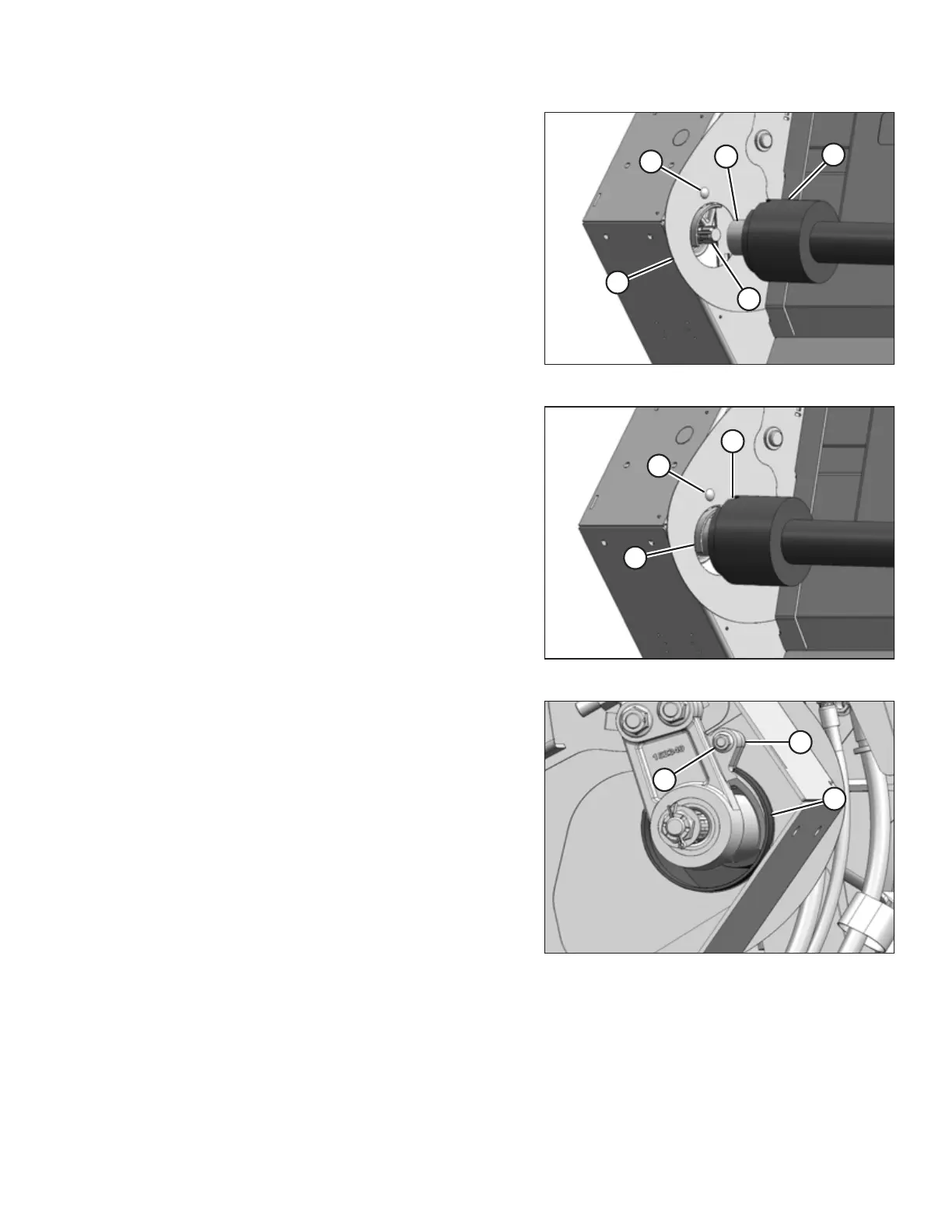
Figure 5.11: Header End of Driveline
2. Pull back guard (A) to expose collar (B) at the header
(notched) end of the driveline.
NOTE:
The driveline may separate if it is not supported at
both ends.
3. Pull back collar (B). Slide the coupler onto splined input
shaft (C) until it locks. Release collar (B).
4. Loosen bolt (D) and move plate (E) (if necessary) to provide
sufficient clearance for the driveline guard.
Figure 5.12: Header End of Driveline
5. Line up notch (A) in the driveline’s rubber bellows with
bolt (B) so that the notch fits around casting (C) inside the
auger drive compartment.
Figure 5.13: Driveline Shield
6. Sandwich lip (A) on the driveline bellows between the hole
in the endsheet and casting (B).
7. Tighten bolt (C).
MAINTENANCE AND SERVICING