215575 313 Revision B
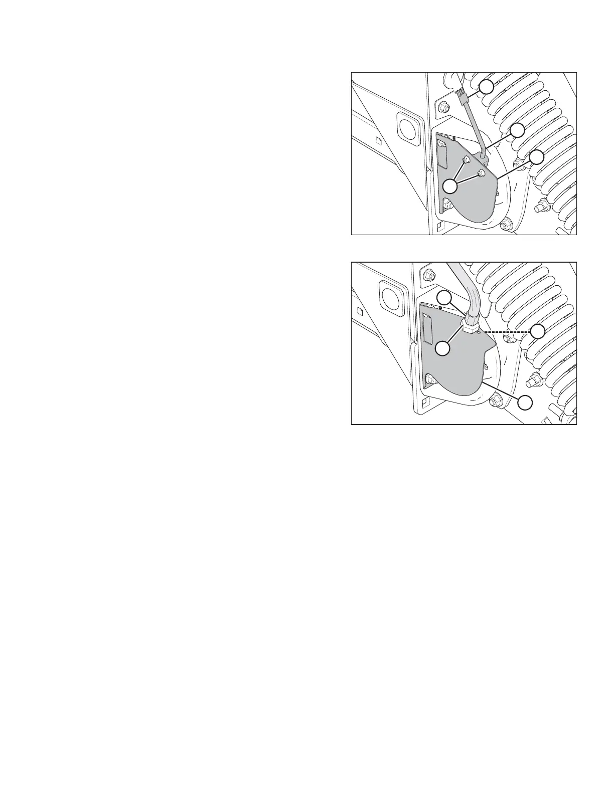
Figure 5.214: Draper Speed Sensor
4. If your pick-up header is configured for an AGCO combine:
Remove bolts and nuts (A), and remove sensor (B) from
support (C).
5. Disconnect the sensor wire from the harness at
connector (D).
6. Attach connector (D) on new sensor (B) to the harness.
7. Position sensor (B) in support (C), and secure with bolts and
nuts (A).
8. Adjust the clearance between the sensor and the sensor
disc. Refer to 5.10.2 Adjusting Draper Speed Sensor, page
311 for instructions.
Figure 5.215: Draper Speed Sensor
9. If your pick-up header is configured for a non-AGCO
combine: Remove lower jam nut (A), and pull sensor (B)
from support (C).
10. Disconnect sensor (B) from the harness and remove top
jam nut (D).
11. Attach new sensor (B) to the harness and install top jam
nut (D) onto the sensor.
12. Position sensor (B) in support (C) and secure it with lower
jam nut (A).
13. Adjust the clearance between the sensor and the sensor
disc. Refer to 5.10.2 Adjusting Draper Speed Sensor, page
311 for instructions.
14. Install the right endshield. For instructions, refer to 3.3.6
Installing Right Endshield, page 30.
MAINTENANCE AND SERVICING