215575 29 Revision B
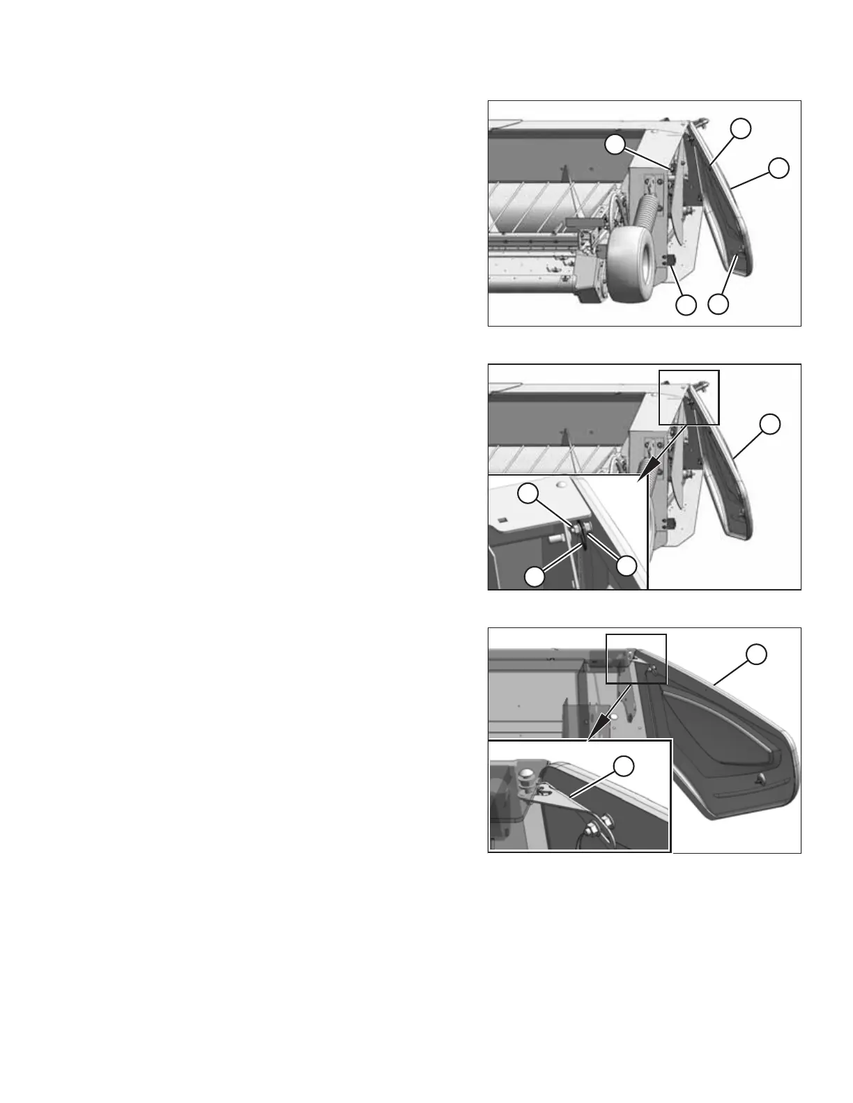
Figure 3.10: Aligning Endshield
5. Close endshield (A), ensuring that magnet (B) and stop (C)
in the header frame are aligned. Doing so will ensure that
latch (D) aligns with receptacle (E).
NOTE:
The positions of latch (D) and magnet (B) are factory-set
and should not require adjustment.
6. If adjustment is necessary, loosen the nuts on the clips
installed in Step 3, page 28 and reposition endshield (A).
Tighten the nuts.
IMPORTANT:
Do NOT overtighten the nuts on the clips. Overtightening
the nuts can damage the endshield.
Figure 3.11: Attaching Support
7. Open endshield (C) slightly so that support (B) can be
installed onto the endshield. Check that washer (D) is
between the support and the endshield.
8. Install nut (A), leaving a gap of 8–10 mm (5/16–3/8 in.)
between the nut and washer (D), which allows support (B)
to move.
Figure 3.12: Endshield Support
9. Move endshield (A) slightly so that support (B) can be
moved out of the locked position.
OPERATION