4C-12 - CHARGING SYSTEM 90-823225--1 1096
4. Remove two brush/regulator attaching screws
and remove brush/regulator assembly.
72823
b
c
d
a
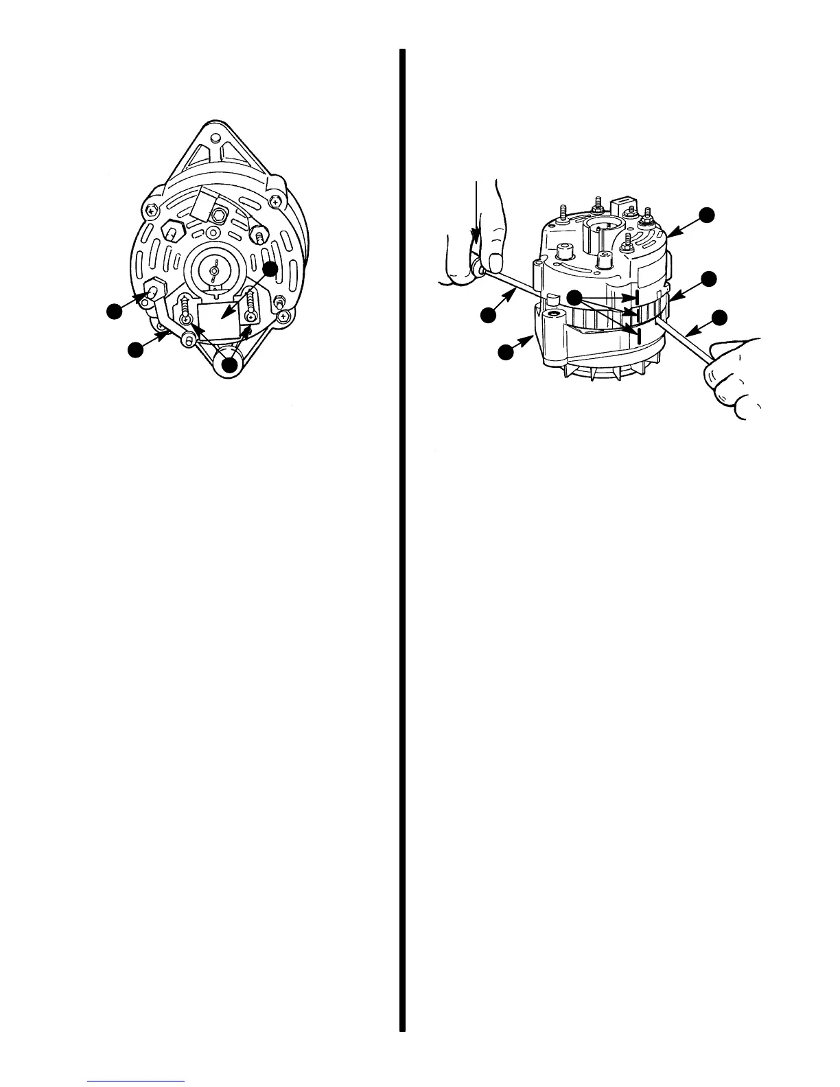
a - Screws
b - Brush / Regulator Assembly
c - Stud Cover Insulator
d - Tie Strap
5. Scribe a mark on rear end frame, stator and front
end frame to ensure proper reassembly later.
6. Remove four screws which secure end frames
and stator together.
IMPORTANT: DO NOT insert screwdriver blades
more than 1/16 in. (1.5 mm) into openings (in next
step), as stator windings may be damaged.
7. Separate rear end frame and stator assembly
from front end frame and rotor assembly using
two thin blade screwdrivers (positioned 180 de-
grees apart from one another) at the locations
shown. Use the two slots shown to initially sepa-
rate units.
72824
b
c
d
e
a
a
a - DO NOT Insert Screwdriver Blades More Than 1/16 In.
(1.5 mm) Into Slots.
b - Rear End Frame
c - Stator
d - Front End Frame
e - Scribe Marks
8. Place rear end frame and stator assembly on the
bench with stator downward. Be sure that bench
is clean and free of metal chips. Remove nuts,
washers, insulators and condenser from output
and ground studs.

 Loading...